DMC specified machine vision hardware and programmed a custom real-time application to perform high-speed inspection of complex folding cartons. Folding cartons for products like beverage carriers often require many folds, flaps, and complicated glue patterns. The cost of an improperly folded or glued carton can be high since the cartons are filled with bottles by an automated production line. The packaging company is liable for any downtime or broken bottles caused by a bad carton.
Machine Vision Hardware
Since DMC’s customer wanted to package the inspection system and incorporate it into their existing packaging line, keeping hardware costs low was a priority. DMC and the customer created a custom real-time PC from standard components and installed the LabVIEW Real-Time operating system to run the application. Each GigE camera is connected to a dedicated network adapter. Inputs on the PCIe-8255R FPGA card connect to encoder and trigger signals from the packaging machine. FPGA outputs control the cameras and lights.
Image Acquisition and Results Tracking
The glue is often applied in two or more stages, requiring multiple inspection stations. Due to machine components that block the view from a single camera, each station may comprise two cameras, up to a total of four cameras connected to one vision controller. Since the cartons may vary in size and length, a line scan camera acquires images of variable size. Line scan cameras also simplify lighting, since it requires a single line of illuminationrather than a large 2D area. A concentrated line light helps keep exposure times low, allowing for high-speed image acquisition.
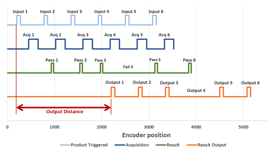
Each carton passes a photoeye to trigger the camera(s). A program running on the FPGA tracks the trigger signal and encoder position. After the inspection system determines a pass/fail result, the FPGA sends an output signal at a specified position on the line to signal to the packaging system that the carton is good. The packaging equipment rejects any carton that doesn't have a pass signal. The timing diagram below illustrates the relative timing between the input trigger signal, image acquisition, pass/fail result determination, and output signal to the system.
User Interface
The customer uses an existing Windows application to configure their folding and gluing machines. The customer wanted to seamlessly integrate a user interface developed by DMC without requiring DMC to modify over their existing source code. To accomplish this goal, DMC developed a .NET application that is called by the existing application and covers a portion of the interface while it is active. The .NET application communicates with the LabVIEW Real-Time application via TCP messages to send configuration information down to the controller and to receive images (with result overlays) for display to the user.
Inspection Algorithm
The vision system checks the position of glue lines to verify proper glue application. The ideal glue positions and tolerances for each glue line are configurable per product (see the next section). The software creates a “Region of Interest” for each expected glue line. For each region of interest, the inspection algorithm verifies the following:
- Glue is present
- Glue starts within tolerance
- Glue ends within tolerance
- Glue width is within tolerance
- Gaps in glue (for dot patterns) are smaller than the maximum tolerance
The system also checks that there is no glue found outside of an expected region. Usually, unexpected glue is a bad thing. In some cases, glue is tolerable in a certain region but not required. The system allows the user to create a region that is ignored.
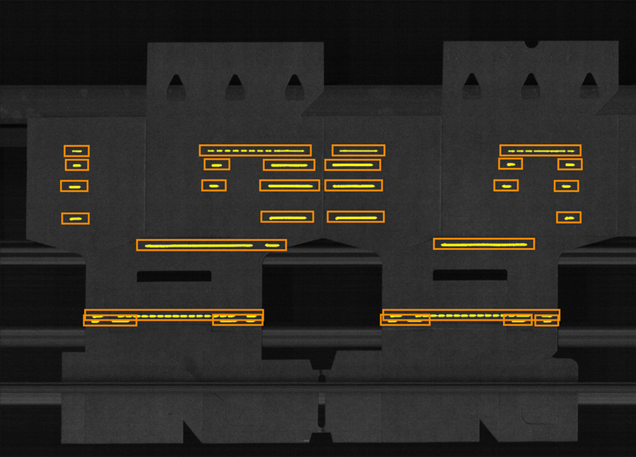
The image below shows glue lines detected by the system (in yellow), surrounded by the “Region of Interest” for each glue line (in orange).
Inspection Configuration
The inspection system needs regions of interest defined to perform the inspection described above. To configure the ROIs, the user has two options:
- Automatically “learn” ROIs based on several cartons
- Manually configure ROIs and tolerances
Typically, for a new product, the user will use the “automatic learn” feature. The system analyzes several cartons and creates ROIs around the average glue positions. If the glue on the template cartons deviates too much from carton to carton, the learn process must be retried. After the automatic learn is complete, the user may tweak the auto-generated ROIs to fine-tune the inspection.
Users can save the inspection configuration with a user-defined “job-name.” In the future, if the customer runs the same glue pattern, they can reload the same configuration by selecting the job name from a list on the user interface.
Inspection Result Display
The real-time vision system transmits images with results markup to the .NET application to display inspection results to the user. The system stores the last ten pass and fail images for review by the user. The user can choose different image processing and overlay options to help them analyze the images and determine failure modes.
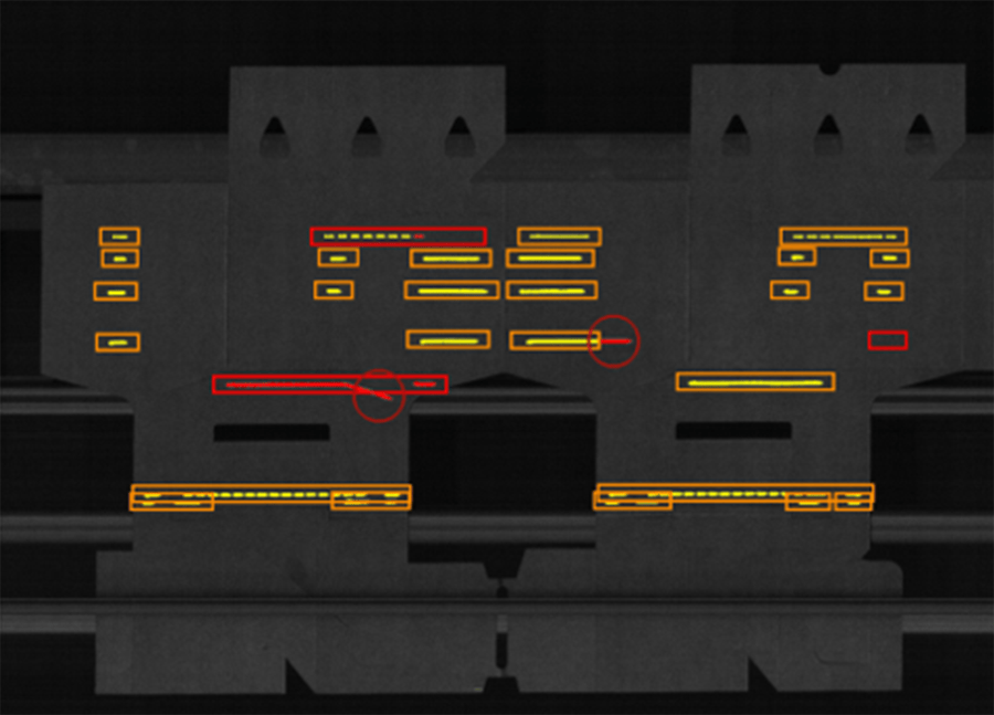
The image below illustrates a failed image with some analysis options enabled. Red highlighting indicates bad glue and failed ROIs. Glue found outside of an ROI is circled because sometimes a speck of glue is hard to see.
Conclusion
DMC combined our expertise in vision systems, LabVIEW development, and .NET development to create a powerful and highly flexible inspection system. DMC's direct customer sells the glue inspection system as an add-on to their existing folding/gluing machines allowing for a competitive advantage over other companies that create packing machines. End-customer facilities all around the world have the system installed.
Learn more about DMC's vision systems, LabVIEW development, and application development services.