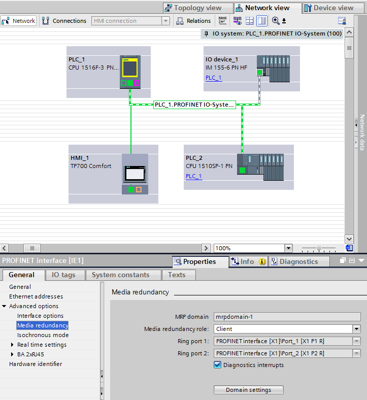
One of the great, and underused, features in TIA Portal is the Network Topology tab of "Devices and Networks." It can enable you to accomplish a number of advanced tasks while simultaneously providing more in-depth network diagnostics. Today, I want to quickly show you how you can use Network Topology to configure a MRP-based Ring Network in TIA Portal.
Why Ring Topology?
There are many reasons why one might consider using a ring topology for your network. The most common one is to provide a semi-fault tolerant network that can handle the break or loss of any one leg of your network by utilizing redundant physical connection paths between network nodes. For a controls network, this can provide an additional layer of security and safety where machine availability is important.
MRP (Media Redundancy Protocol) is a redundancy protocol supported by all Profinet capable devices that will allow a network to be configured in a ring topology. Since Profinet is an open standard, this means that MRP is a manufacturer independent protocol and can be used to form a ring with devices from different manufacturers (so long as all devices are fully IEC 62439 compliant). If you're interested in the details of how it works, Wikipedia has a good and short overview.
In the example below, we will use MRP and the Network Topology tab to configure a ring topology for an automation network. While the most common scenario would be to add a switch into the mix (such as a SCALENCE switch), I don't have one available for testing so I'm just going to use an S7-1516F-3PN PLC, S7-1510SP-1PN PLC, an IM155-6 PN remote I/O rack, and a 7" Comfort Panel. All of these devices have at least 2 switched ports and support MRP which will allow us to configure a small ring.

Step 1: Configure the Network Interfaces of All the Devices
In my project, I've already added all of my devices to my project. The first step will be to open up "Devices and Networks" to the Network tab and configure all of their interfaces. For this example, I'll use the default IP addressing scheme.

In your network view, connect the interfaces of all devices to create a common Profinet network. This will allow all of our devices to talk to one another. I've also added a DO card to my ET200SP I/O remote rack and created HMI connections for both PLCs to the TP700 Comfort Panel.
Step 2: Configure the Network Topology
While it's possible to configure MRP without using topology, I find it makes it much simpler and aids in troubleshooting in the event of a network fault. To do this, navigate to the Topology tab of the "Devices and Networks" view.

Configure the topology to create a ring - I've used the port connections shown below, daisy chaining Port 2 from each device to Port 1 of the following and closing the loop back to the beginning.

Step 3: Configure MRP
Within an MRP ring, each device must be assigned a role. One device will be the MRP Manager and will be responsible for sending out test frames to detect for a network failure and for blocking network traffic on one port (except for the test frames) to prevent a network loop. The other devices must be assigned a Client role so they know how to handle the test frames.
In this example, I will use the S7-1516F-3PN as my Manager, and will set all other devices to be Clients. You can assign roles in several ways - the easiest way for me is to go to the Device View for each device and look at the properties of the network interface. Under "Advanced Options," look for Media Redundancy. Here you can select a role for the device (Manager or Client) and enable diagnostics interrupts. If you choose to enable diagnostic interrupts for all devices, note that you can now detect the status of your MRP ring within your program from OB82.


Step 4: Download and Configure All of the Devices
Start by first connecting all but one link of your network (don't close off the ring just yet until all of the devices are configured to handle it). In my case, I daisy chained the S7-1516F, IM155-6, TP700 and S7-1510SP together without connecting the S7-1510SP back to the S7-1516F. Download to each PLC and the HMI, and set the Profinet name of the IM155-6. Now, you are ready to close the loop to create your MRP ring.
Step 5: Test
As a simple test, I enabled the Clock Bytes on both PLCs and configured the 1510SP to function as an I-Device. In my shared data area, I passed over the 1Hz Clock bit from the 1510SP to the 1516F PLC. Now, on the 1516F I added two simple rungs of logic to OB1 to pulse two outputs on the IM155-6PN - one pulsing from the 1Hz Clock bit of the 1516F and the other pulsing from the clock of the 1510SP. Finally, I added a System Diagnostics View to the HMI so I could monitor my network.
After going online with the two PLCs (I'm connected through the third port on my 1510SP), I can verify on the Topology tab of "Devices and Networks" that my MRP ring is connected as configured. I can also watch the outputs on the remote I/O rack to verify that both outputs are pulsing as expected.

Now let's do some testing. Disconnect any one connection and verify that both outputs continue to function as expected. You can also note, from the integrated fault lights on the devices or from the Diagnostics Viewer on the HMI, that a downed network connection is detected and reported.

That's about it - you now have a working MRP ring! I hope this is helpful! If you're looking for help, please take a look at our Siemens PLC Programming Services or Contact Us today!