Introduction
This tutorial covers the creation of a simple embedded project from the ground up that allows an ST Nucleo development board to talk to your PC using UART serial communication. It is used at DMC to introduce new engineers or engineers who primarily work in other service areas to embedded project work and covers a range of topics, skills, and tools commonly used in DMC Embedded projects including:
- An Eclipse-based IDE (TrueSTUDIO)
- Wiring hardware
- Configuring MCU peripherals (UART in particular)
- Reading schematics and documentation
- CubeMX software
- A serial communication viewer (RealTerm)
Hardware
The following hardware is required:
- USB to TTL UART Converter
- (3) Female to Female Jumper Wires
- STM32 Nucleo Development Board*
- USB Mini B Cable
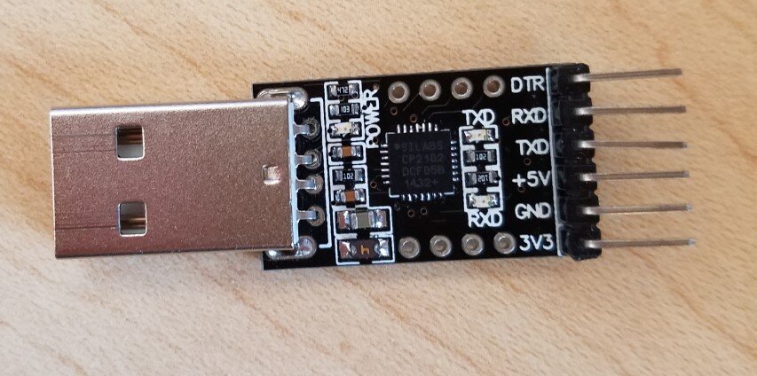
USB to TTL UART converter
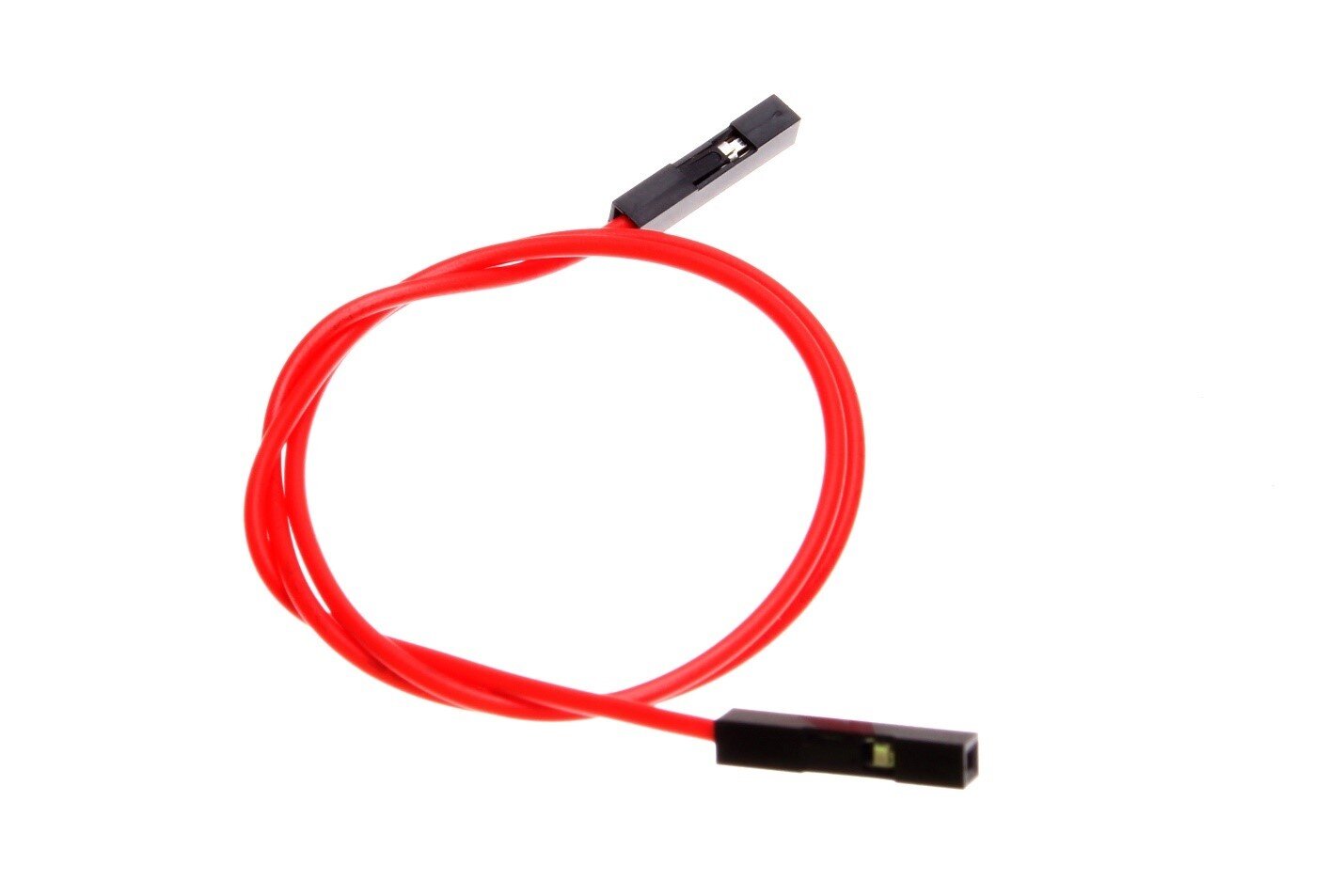
Female to Female Jumper Wires
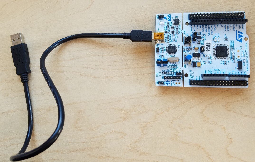
STM32 Nucleo Development Board* and USB Mini B Cable
*Note the board type! You might have an -F103RB, or an -F303RE, or something else! If your development board is not labeled, the chip name is engraved on the chip in the center.
Software
Install the following software:
Documentation
Download the following documentation:
Template Project
- To generate the template project, open CubeMX and click New Project.
In the Board Selector tab, look for the Nucleo board with the Vendor, Type of Board, and MCU Series dropdowns.
- Select Nucleo64 from the Type of Board dropdown (yes, it’s a 32-bit microcontroller that is named Nucleo64). Open the MCU series dropdown and select STM32F1 if you have an F103RB, or select STM32F3 if you have the 303RE.
- Finally, select the board that pertains to your model from the Boards List, and hit OK.

New Project Menu
You should see a nice graphical interface appear, which we will use to set up our pins.
- We are going to use USART1, so click on the + to the left of the name to open it up, and set it to Asynchronous Mode.

You’ll see that the graphic of the chip in the center will change and two pins on the right will change color to green (gray means that the pin is not configured to anything). By default, port A pin 10 is RX and port A pin 9 is TX.
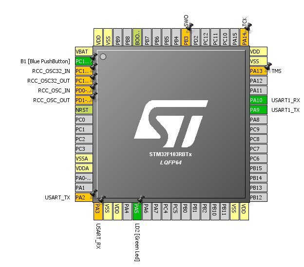
- Navigate to Project -> Generate Code. Give your project a name, pick a Project Location for your project, and select TrueSTUDIO from the Toolchain/IDE dropdown menu.

Project Settings Menu
- In the Code Generator tab, select Generate peripheral initialization as a pair of ‘.c/.h’ files per IP.

Project Settings Menu
- Hit Open Project at the popup prompt and your project should open up in TrueSTUDIO.
- You may get a popup explaining you need a firmware package. If so, click Yes to download it and wait for it to finish.

Writing the Program
- Open the newly generated TrueSTUDIO project.
CubeMX has generated a very simple project with some basic settings for you.
- In the Src folder, open gpio.c.
You’ll see a configuration for the USER pushbutton pin which is labeled B1 on the development board, but this is NOT port B, pin 1 on the chip. You’ll also see our UART TX and RX pins and LED 2.
GPIO_InitTypeDef GPIO_InitStruct;

/* GPIO Ports Clock Enable */
__HAL_RCC_GPIOC_CLK_ENABLE();
__HAL_RCC_GPIOD_CLK_ENABLE();
__HAL_RCC_GPIOA_CLK_ENABLE();
__HAL_RCC_GPIOB_CLK_ENABLE();

/*Configure GPIO pin : PtPin */
GPIO_InitStruct.Pin = B1_Pin;
GPIO_InitStruct.Mode = GPIO_MODE_EVT_RISING;
GPIO_InitStruct.Pull = GPIO_NOPULL;
HAL_GPIO_Init(B1_GPIO_Port, &GPIO_InitStruct);
- To view our UART configuration, open the usart.c file and look for the MX_USART1_UART_Init function.
Our UART is configured with a baud of 115200, 8 bits per word with 1 stop bit, no parity, and some other features. Remember this for later. We’ll need to configure the same settings on the PC side.
void MX_USART1_UART_Init(void)
{

	huart1.Instance = USART1;
	huart1.Init.BaudRate = 115200;
	huart1.Init.WordLength = UART_WORDLENGTH_8B;
	huart1.Init.StopBits = UART_STOPBITS_1;
	huart1.Init.Parity = UART_PARITY_NONE;
	huart1.Init.Mode = UART_MODE_TX_RX;
	huart1.Init.HwFlowCt1 = UART_HWCONROL_NONE;
	huart1.Init.OverSampling = UART_OVERSAMPLING_16;

}
- Navigate to the main.c file and scroll down to the main() function.
CubeMX automatically wrote in our initializations for us and an infinite while loop that currently does nothing.
int main(void)
{
	/* USER CODE BEGIN 1 */

	/* USER CODE END 1 */

	/* MCU Configuration----------------------------------------------------------*/

	/* Reset of all peripherals, Initializes the Flash interface and the Systick. */
	HAL_Init();

	/* Configure the system clock */
	SystemClock_Config();

	/*Initialize all configured peripherals */
	MX_GPIO_Init();
	MX_USART1_UART_Init();

	/* USER CODE BEGIN 2 */

	/*USER CODE END 2 */

	/*Infinite loop */
	/* USER CODE BEGIN WHILE */
	while (1)
	{
	/*USER CODE END WHILE */

	/*USER CODE BEGIN 3 */

	}
	/* USER CODE END 3 */

}
We will fill the while loop with code that will send “hello world” through UART whenever we push the blue USER pushbutton.
We need a function that will allow us to read the pushbutton state and a function to send our message over UART. Such functions exist in the HAL library. STM’s HAL layer allows us to use the same functions regardless of the particular STM chip we are using, minimizing the number of changes we would have to make if we changed chips. It also encapsulates a lot of the lower layer hardware details that we might otherwise have to worry about.
- Open the STM32F3 HAL datasheet that you downloaded and find the GPIO Generic Driver chapter. Scroll down to the list of functions, and find the description for HAL_GPIO_ReadPin which takes the port and pin of interest and returns its state.
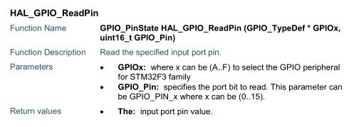
- Locate the UART Generic chapter and find the function for transmitting for UART in blocking mode, HAL_UART_Transmit. The function takes the address of a UART handle, a pointer to the data buffer, the size of the data buffer, and a timeout.
CubeMX named the handle husart and filled out its attributes in usart.c.

- Pass this handle in to HAL_UART_Transmit. For the timeout, you can pick any value you want. 10,000 ticks should be sufficient.
- Try to use these two functions to write code in your main function so that whenever the pushbutton is pressed, a “hello world” message will be transmitted through UART. When you think you’ve got working code, go on to the next step to compile it.
Below is an example implementation, but feel free to use your own.
int main(void)
{
	HAL_Init();

	SystemClock_Config();

	MX_GPIO_Init();
	MX_USART1_UART_Init();

	while (1)
	{
		if (HAL_GPIO_ReadPin(B1_GPIO_Port, B1_Pin))
		{
			UART_TransmitHelloWorld();
		}
	}
}
HAL_UART_Transmit requires a UART handle that is private to usart.c, so I wrote a public function, UART_TransmitHelloWorld(), that uses HAL_UART_Transmit to send the message over.
void UART_TransmitHelloWorld()
{
	char message[] = "hello world\r\n";
	HAL_UART_Transmit(&huart1, (unit8_t*)message, strlen(message), 1000);
}
Compile Your Code
Although what we want to do seems simple and should only take a few lines of code, you’ll need to understand how pointers, addressing, and file scope works in the C language to implement this.
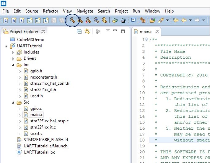
- Click on the Build Button to build your project.
If you are able to build successfully, you’ll have no errors on your console at the bottom.
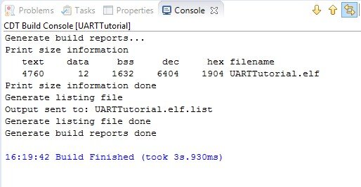
- Locate any errors in the Problems tab. You’ll be able to double click on the error to get to the line the compiler is complaining about (this works on most, but not all, error messages). Go to the next step once you have a successfully compiling project.
Wire Things Up, Plug Things In
Now we need to wire up the Nucleo Board to the PC.
UART communication requires a TX pin, an RX pin, and a ground pin, but where are these pins on the Nucleo board?
If you recall, with CubeMX, we had set port A pin 10 as RX and port A pin 9 as TX. You can also find these settings in the HAL_UART_MspInit() function in the automatically generated usart.c file to verify that this is indeed the case.
GPIO_InitTypeDef GPIO_InitStruct;
if(huart->Instance==USART1)
{
/*USER CODE BEGIN USART1_MspInit 0 */

/*USER CODE END USART1_MspInit 0 */
	/* Peripheral clock enable */
	__HAL_RCC_UART1_CLK_ENABLE();

	/**USART1 GPIO Configuration
	PA9     ------> USART1_TX
	PA10     ------> USART1_RX
	*/
	GPIO_InitStruct.Pin = GPUI_PIN_9;
	GPIO_InitStruct.Mode = GPIO_MODE_AF_PP;
	GPIO_InitStruct.Speed = GPIO_SPEED_FREQ_HIGH;
	HAL_GPIO_Init(GPIOA, &GPIO_InitStruct);

	GPIO_InitStruct.Pin = GPUI_PIN_10;
	GPIO_InitStruct.Mode = GPIO_MODE_INPUT;
	GPIO_InitStruct.Pull = GPIO_NOPULL;
	HAL_GPIO_Init(GPIOA, &GPIO_InitStruct);
So, where are these pins on the board?
- Open up the Nucleo pinout document that you downloaded earlier. Scroll down to the pinout of your Nucleo board to see how the header pins connect to the microcontroller.
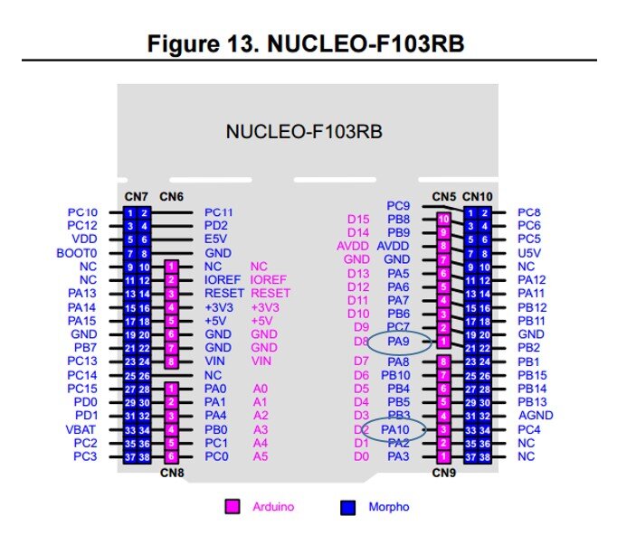
- Connect TX on the Nucleo (A9) to RX on the USB-to-UART converter.
Nucleo TX -> USB-to-UART RX
- Connect RX on the Nucleo (A10) to TX on the USB-to-serial converter.
Nucleo RX -> USB-to-UART TX
- Also, connect the ground pin on the USB-to-UART converter to any ground pin on the Nucleo board.
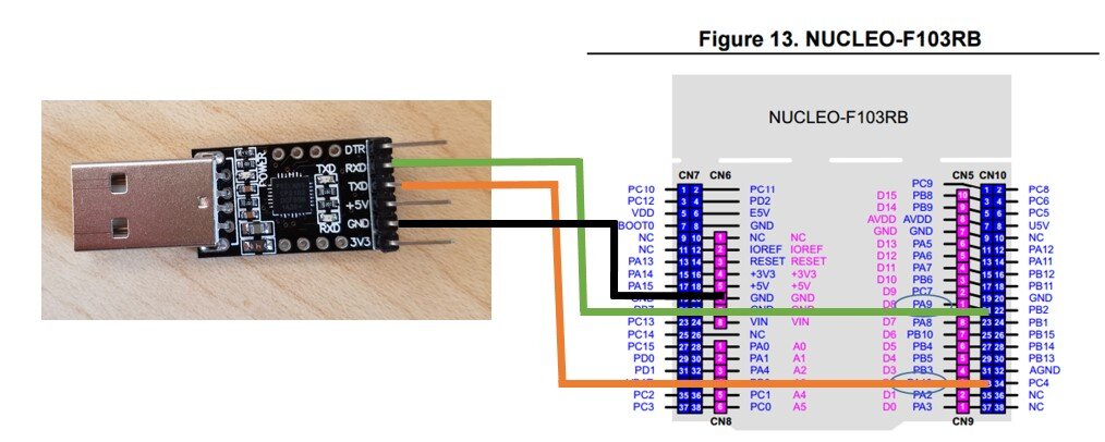
The transmitter (TX) of the Nucleo goes into the receiver (RX) of the USB-to-UART dongle. The same reasoning applies to the RX of the Nucleo.
- Finally, plug in the Nucleo board to your PC’s USB, and plug in the USB-to-UART converter to your PC as well.
It should look something like this:

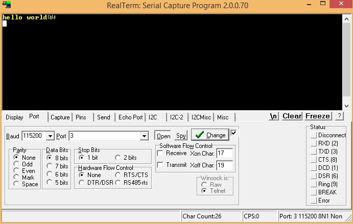
Realterm
- Open up Device Manager and look in the Ports tab. Find the COM port that your USB-to-UART converter is connected to. Mine is COM3. Yours may be different. Remember this COM port.

Realterm is a program that will allow your computer to send and receive serial communication through your PC’s ports.
- Open up Realterm. In the Port tab, select 115200 baud.
Recall that we configured the Nucleo board’s baud to be 115200, and that the baud must match between the Nucleo board and the PC.
- Select the COM port your USB-to-UART converter is connected to in the Port dropdown.
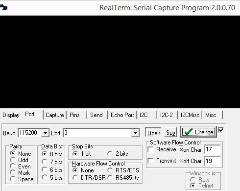
Notice that most of the other settings we would need to configure are, by default, matching the Nucleo’s UART configuration (8 bit of data, 1 stop bit, no parity), so we shouldn’t need to adjust those.
Now let’s upload our program to the Nucleo board.
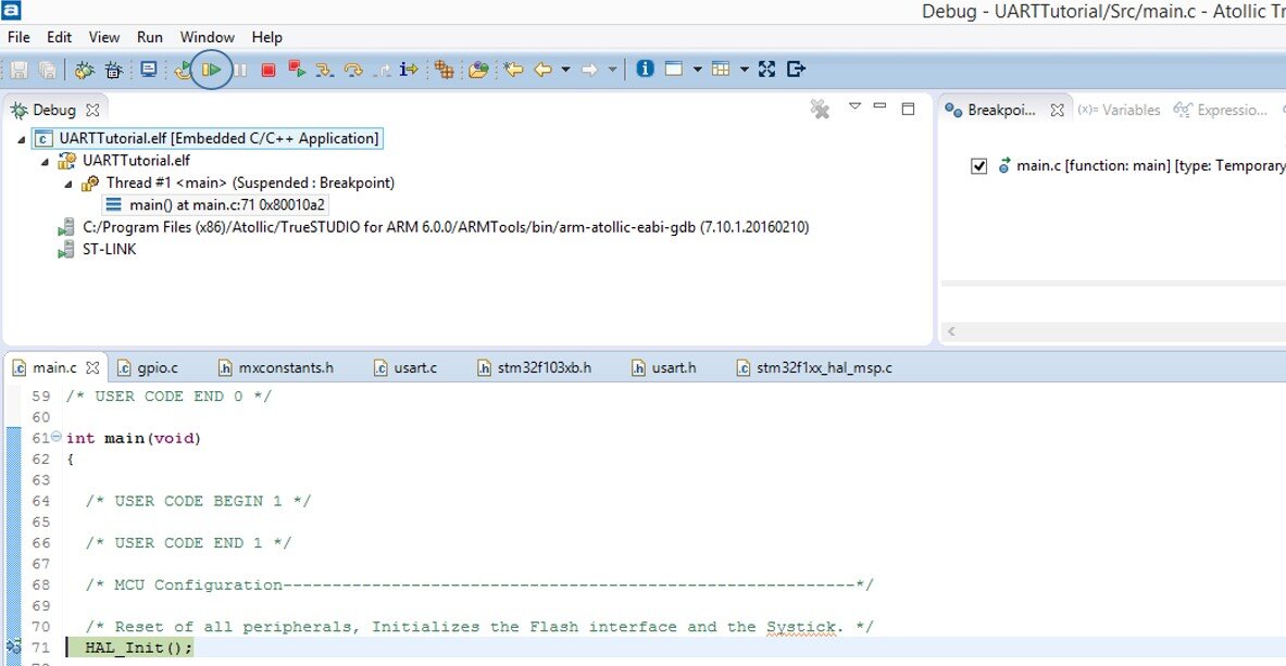
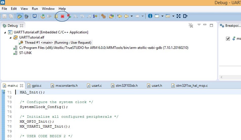
- Go back to the TrueSTUDIO project and click the Debug button at the top.

TrueSTUDIO will go into the Debug mode and should automatically create a breakpoint at the top of main().
- Click the Resume button to proceed past the breakpoint.
- Go back to your Realterm window.
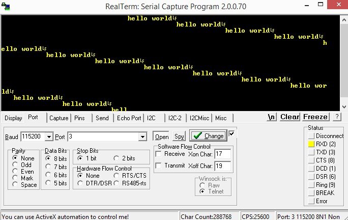
Depending on how you wrote your code, a number of things may be happening. Nothing might be happening, or a bunch of messages might be spamming the window.
- Hit the blue USER pushbutton on the Nucleo and see if anything changes.
- Go back to the project and change the code in the main() function so that the hello world message only pops up once if you push the blue USER pushbutton.
The terminate button in the Debug window will allow you to exit Debug mode so that you can recompile your code.
If you’ve got that working, then congrats! You’ve successfully completed your own small embedded systems project from the ground up.
Check out this Nucleo UART Tutorial mbed-Style for a hands-on introduction to embed that makes use of this same project.
Learn more about DMC's Custom Software and Hardware Services or Contact Us to start building a solution.