If you find yourself working with Analog IO on the Siemens S7-1200 for the first time, you may wonder how and where to start. Here are some basic tips for working with Analog IO on this PLC platform. For the purposes of this blog, I will focus on implementing 4-20mA inputs and outputs, but the concepts should apply to other signal types as well.
Configuring Analog Input/Output Models:
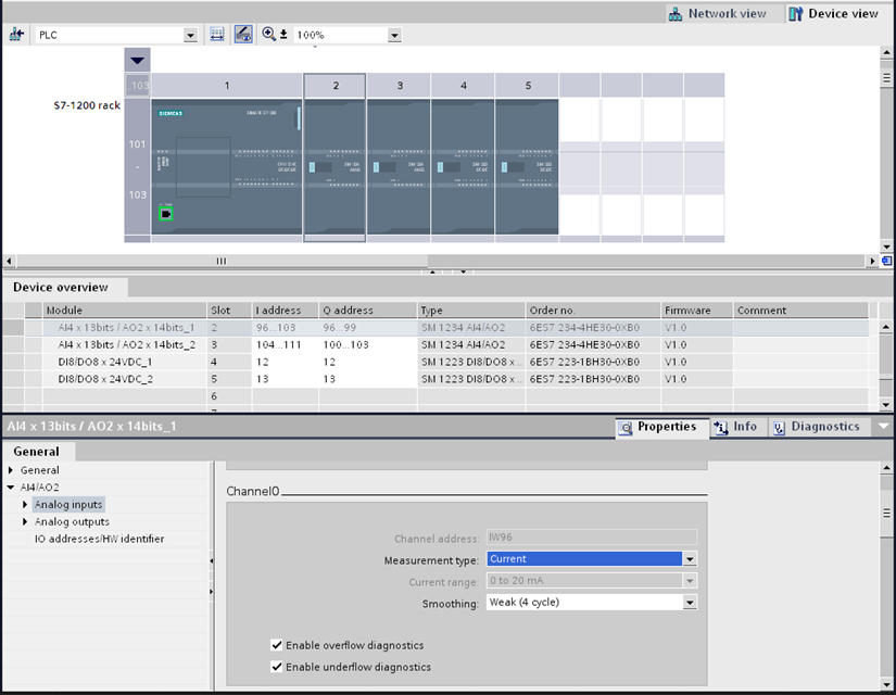
Open the Device Configuration for the PLC. Add your module, then configure each channel's properties. Not that for current-based signals, the only range available is 0-20mA. If your signal is 4-20mA, still configure it as 0-20mA and scale the input value as demonstrated below.

Reading an Analog Input Value:
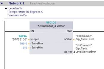
Since DMC engineers are biased toward modular, flexible code, I wrote my own function block to process a 4-20mA analog input that I can re-use within the project and for future projects.

I pass in all the unique values for that sensor that are required for scaling, and pass out my scaled, engineering value along with an error indicator.
Inside my function block, I first test to make sure that the raw input value from the analog input channel is within the normal operating range and set the error output if it is not. The raw input value ranges are listed in section A.6 of the S7-1200 Easy Book located on the Siemens website.
For the sake of convenience, here are the value ranges:
Overflow = 32512 to 32767
Undershoot = 0 to -4864
Underflow = -4865 to -32768
Decimal Range:
0.0 - 27648.0
Wire break limits:
4mA = 5529.6
3mA = 4147.2
2mA = 2764.8
1mA = 1382.4
After the input validity test, it's time to convert the raw input to a meaningful engineering value. For 4-20mA input signals, Siemens supplies a library function to convert the 0-20mA to a 4-20mA range. The library functions are available on the Siemens website with instructions here: Using the Siemens 0-20mA / 4-20mA conversion blocks.
Note: I highly recommend modifying the standard library function "Scale_current_input" as shown below to handle a negative input value before the value is converted to a real number.

Once you have an accurate 4-20mA raw value range, perform the linear scaling math to generate your meaningful engineering value. For example: Output = Input((Max-Min) / Range) + Min
Writing an Analog Output Value:
Writing an analog output is a bit simpler than reading the analog input. Simply convert your analog output value to a percentage (0-100) and input that percentage into the "Scale_analog_output" library function provided by Siemens (see link above). The resulting word value can be sent directly to the analog output address.

In Summary:
With a little help from the Siemens library blocks for converting 0-20mA signals to 4-20mA signals, analog IO on an S7-1200 controller is mostly straightforward. I’ve tried to cover all the main points, but if there are any additional details that you’d like covered, feel free to leave me a comment.
Learn more about DMC's PLC Programming services and contact us to get started on your next PLC Programming project.