In the automation world, machine and process safety are of the utmost importance. When a risk assessment requires it, specialized safety hardware and software may be necessary to minimize the risk to people and equipment. Unfortunately, understanding safety hardware and safety programming can be challenging without proper training and experience.
The goal of this blog series is to provide insight into the TwinCAT development process so that when you build your TwinSAFE program, you are properly informed about the program you are developing.
Machine safety is a serious matter. When you are architecting your safety program, please make sure you are qualified to verify the safety of the system or are consulting a certified safety expert who can work with you to make sure your system is safe. If you are not properly equipped to develop a system on your own or would like assistance from our certified safety experts, please feel free to contact us for help developing your safety solution.
Introduction
This article assumes that you have already created your TwinCAT project and configured the basics, such as Alias Devices and Group Ports. If you have not, please refer to Creating and Configuring a Project from Scratch before continuing.
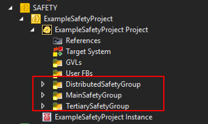
When developing a safety program in TwinCAT, it’s important to understand the terminology and structure. TwinSAFE programs are split into a series of TwinSAFE Groups. TwinSAFE Groups serve a purpose similar to a task in a standard project. Each TwinSAFE Group has its own operational status and logic- TwinSAFE Groups can operate independently of one another or in tandem:
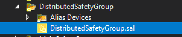
Each TwinSAFE Group contains a “.sal” file that contains the safety logic. This file consists of a series of networks that serve as a visualization of the function blocks and variable connections. It is from this file that you will develop your safety program:
The remainder of this post will focus on the development of the logic within these “.sal” safety logic files. Discussion topics will include the following:
A Note About TE9000 Versions
Beckhoff actively updates and releases new builds of its software offerings, and TwinSAFE is no exception. It is highly recommended to use the latest build of the TwinCAT 3 Safety Editor, also known as TE9000. A link to download the latest build can be found here.
As for this writing, the most recent build is version 1.4.8. If you are using an outdated version of TE9000, it is likely that you will be missing the ability to integrate the latest safety hardware and firmware revisions.
For example, it is necessary to use TE9000 1.4.8 or newer to use an EL1918 card as both a safety logic processor and an IO card. TE9000 1.4.8 or newer is also required to use ELM 72xx servo drives in a safety project.
Adding and Configuring Function Blocks
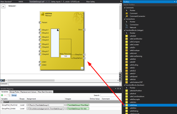
Function blocks can be added from the Toolbox window. Blocks can be dragged from the toolbox into the safety logic networks:
The name of a function block can be edited by clicking on it. You can do the same with the names of networks.
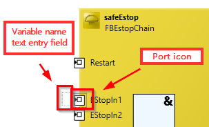
Editing inputs and outputs can be done by directly typing the name of a variable into the text entry field adjacent to the port icon (this is hidden but will appear if you click next to the port icon), or you can double click on the port button to create a connection to the input/output of another function block:
Changing Function Block Input Behavior
Some ports have configurable behavior, depending on the type of function block. You can locate the port configuration by right-clicking on the port icon and selecting “Change InPort Settings”. In the Estop example, each pair of inputs can be configured to operate as a dual channel, individual channel, or disabled port. By default, all the ports on this block are disabled and need to be configured:

Many function blocks have configurable InPort settings. Some common options are dual-channel monitoring, timeout settings, and input negation (NO vs NC evaluation). These options are not clearly advertised on the function block in the editor, so make sure to check the documentation for each function block to see what options exist. The documentation can be found here or on the Beckhoff website.
See the section Using the Estop Block for examples of configured InPorts.
Function Block Execution
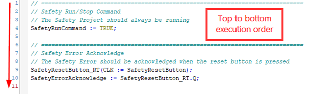
In structured text, the operation of instruction occurs from the top to the bottom, each line occurring before the subsequent one. In ladder logic, rungs also occur in order from top to bottom. However, unlike structured text or ladder, the order of execution of function blocks in a TwinSAFE program is not determined by their positioning in the program:
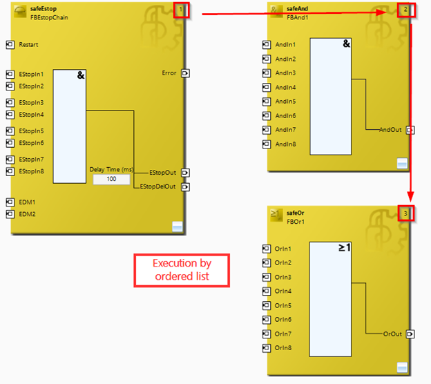
Each TwinSAFE Group has an ordered list called the function block execution order. The function block execution order is independent of their positioning within the program — instead executing based on their position within the execution order list. Their position within the list is indicated by the number in the upper right-hand corner of the safety function block.
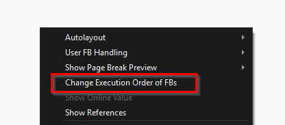
To view and edit the list, you can right-click within the program and select the option “Change Execution Order of FBs”. This will reveal a window that allows you to reorder the operation of blocks within the program:
Ignorance of the function block execution order can lead to unintentional bugs and race conditions within the program. Additionally, programmers may make use of this feature without clearly documenting its use, making the program’s behavior difficult to interpret.
The example below shows a User FB that utilizes the execution order in a “clever” way that makes the program logic unintuitive and prone to errors with future edits:

This User FB monitors a signal (SignalMonitor) for a rising edge. At first glance, it seems that the logic should not work, as the safeAND is monitoring SignalMonitor AND NOT SignalMonitor, meaning the output (RisingEdgeDetected) should never be true. The trick here is that the author of the program has ordered the FBs such that the evaluation of the safeDecouple occurs after the evaluation of the safeAnd.
During execution, the input AndIn2 of the safeAnd is updated at the end of the cycle, meaning that its decoupled value of SignalMonitor is the one from the previous scan. The safeAnd block is really evaluating SignalMonitor (this scan) AND NOT SignalMonitor (last scan), giving us the rising edge detection.
This usage of the function block execution order is not intuitive, makes programs less maintainable, and more prone to bugs. Do not be like this programmer. Use the function block order appropriately.
Using the Variable Mapping
Variable Mapping is a tool that you will use to define and manipulate the assignment and usage of variables. Variables can be created within the TwinSAFE Group by either typing them directly into a function block input or output in the safety logic (XAE shell will automatically add the variable) or by adding a variable within the Variable Mapping window.
Variables can be mapped to function block inputs/outputs or to Alias Devices. This is the main pathway by which you will connect the input and outputs from safety logic to the physical I/O points. While you can connect function blocks to one another directly, variables can also be used for the same purpose — allowing you to connect ports across networks as well.
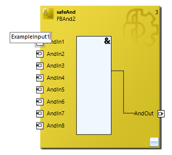
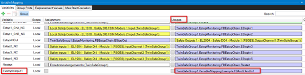
In the following example, a variable is defined in the program by typing it directly into the function block port. Once it has been typed, it will appear within the variable mapping with a listed usage on the corresponding function block:
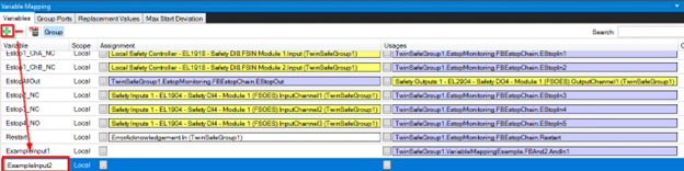
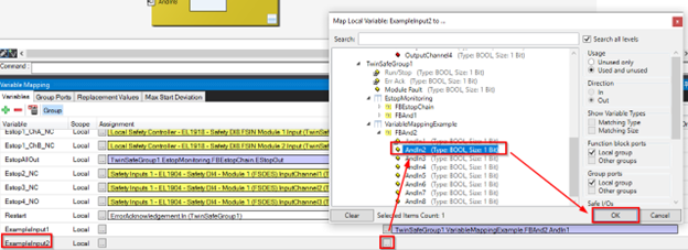
We can also work the other way around. By clicking on the green plus icon, we can add a new variable to the mapping. After the variable has been named, we can specify a usage of the function block input we want. Once “OK” is selected, the variable will appear at the port in the logic:
From the Variable Mapping, we can also tie variables to inputs or outputs from the alias devices with the same technique. Simply open the Assignment or Usage mapping and select the input from the Alias Device:
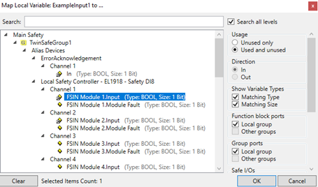

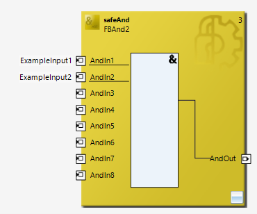
This example now has the first two inputs from the local safety controller tied to the two inputs on the safeAnd block.
Multiple Selection for Usages
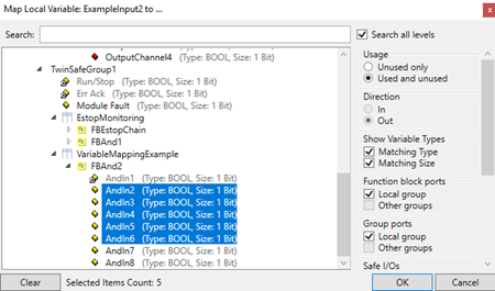
While each variable may only have a single assignment, it can have multiple usages. To select multiple usages from the window, hold “ctrl” while you click:
You may find this useful if you need to use the same status as a reference for a number of function blocks. For example, if you have a localized safety circuit that is responsible for de-energizing a series of devices, the aggregate status of the safety circuit may be used by several function blocks that control the outputs for each of those dependent devices.
Networks
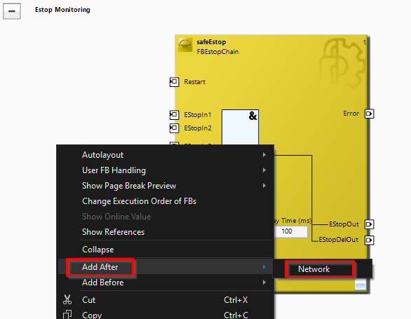
Just like with ladder logic, the safety logic can be organized into networks. To add a network, right-click within an existing one and select “Add After>Network” or “Add Before>Network”:
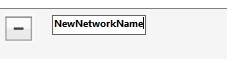
To rename a network, click on the network name and edit the text. Names of networks should be compliant with C variable naming rules (no spaces or special characters):
Using the Estop Block
We will discuss the Estop block, its function, and its configurable settings. For example, The Estop function block determines that an Estop has been pressed; it can change the operational state of the TwinSAFE Group as a whole.
If an Estop output has been latched, it will require a rising and falling edge signal to its “Restart” input. This behavior acts as a safety acknowledgement and prevents automatic restart of the program after the estop input signal has been reset. This input can be linked to either a safety or standard variable, allowing the safety reset to come from the standard program.
The estop block has 8 inputs that can be configured and combined into dual-channel pairs: EStopIn1 / EStopIn2, EStopIn3 / EStopIn4, EStopIn5 / EStopIn6, and EStopIn7 / EStopIn8. The values of the two inputs can only deviate from one another for a configurable time called a delay time. If the delay time is exceeded for any input pair, the FB, and by extension, the entire TwinSAFE Group, will enter the error state. This can only be cleared via the “Err Ack” signal in the TwinSAFE group port:

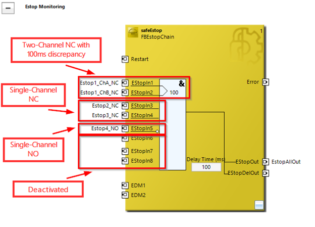
The estop block has three outputs: Error, EStopOut, and EStopDelOut. If Error is true, an input pair has exceeded the delay time or there is an error with one of the EDM inputs. For outputs that need to be immediately set, use EstopOut. EstopDelOut considers the delay time before activating.
The EDM ports (External Device Monitoring) can be used to implement a feedback loop for the outputs of the Estop block. EDM 1 is the feedback loop for EstopOut and EDM 2 is the feedback loop for EStopOutDelOut.
The EDM ports are expecting feedback on the safety circuit response. These inputs should see feedback from contractors indicating that the response to the safety signals has been properly initiated. If the estop function block does not see the proper feedback on its EDM channels, it will force the TwinSAFE Group into an ERROR state, requiring the group to receive the “Err Ack” signal into the group port to return to standard operation.
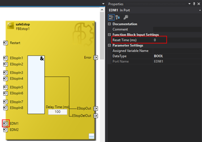
To disable an EDM port, click on EDM1/EDM2 in the FB and set “Reset Time” to 0 ms in the properties tab:
Passing Signals between Standard and Safety
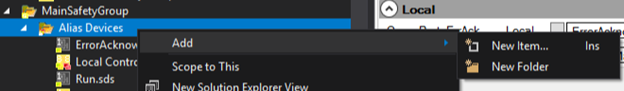
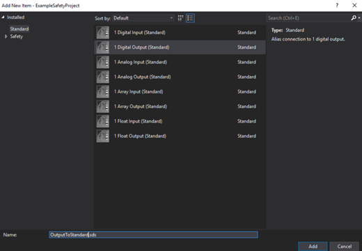
Using Alias Devices, variables can be passed between the TwinSAFE project and the standard project. To begin, create a Standard Alias Device in your safety project by following right clicking the “Alias Devices” folder in the safety project tree, click “Add New Item” and selecting the desired variable datatype from the “Standard” tab. Note that we are using the “Standard” tab as opposed to the “Safety” tab since we are going to be communicating with the standard project:
The Alias Device will serve as an intermediary between a variable in the standard project and a variable in the safety project. You will have to link the Alias Device to both an I/O variable from the standard project and a variable from the safety project. First, select the desired Alias Device from the “Standard Signals” folder in the solution explorer. Then, there will be an option to link the Alias Device to an I/O variable from the standard project. Note that you must select an input variable from the standard project if your Alias Device is an output variable and vice versa.
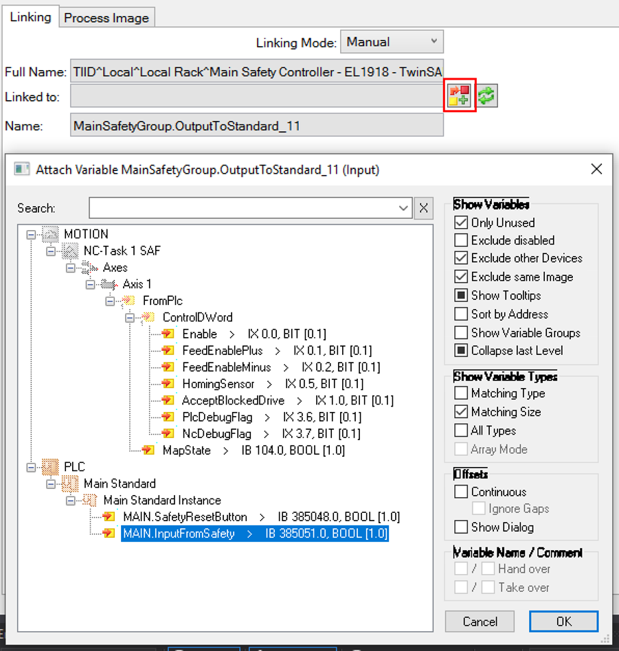
To link the Alias Device to the safety variable, go to the “Variable Mapping” tab in the safety project and click the ellipsis in either the “Assignment” or “Usages” column for the safety variable you want to link to your Alias Device. Input Alias Devices should use the “Assignment” column and output Alias Devices the “Usages” column. Now, your Alias Device is connected to both a standard variable and a safety variable. This provides a useful way of sending information between the safety and standard projects.

Conclusion
With this information under your belt, you now possess the knowledge to develop your safety solution.
Safety is no joke. When you are architecting your safety program, please make sure you are qualified to verify the safety level of the system or are consulting a certified safety expert who can work with you to make sure your system is safe.
If you aren’t properly equipped to develop your own safety solution or want to take your Automation project to the next level, contact us for help developing your safety solution.
Special thanks to Dominic Del’Olio for his contributions to this blog’s content.