TwinSAFE platform offers powerful tools for building safety-critical logic. However, starting a new TwinSAFE project from scratch can feel overwhelming, especially without prior exposure to the safety editor, group configuration, or alias device linking.
This blog walks through the complete process of creating and configuring a TwinSAFE project from the ground up. Whether you're new to safety development or just new to TwinSAFE, this guide will help you navigate the key steps—from setting up your project and selecting the target hardware to linking devices and configuring group ports. As always, if you're unsure about verifying the safety of your system, be sure to work with a certified safety professional or reach out to our team for support.
This process will be broken down into the following steps:
- Initial Project Creation
- Creating TwinSAFE Groups
- Selecting Project Target
- Linking Safety Hardware
- Configuring Group Ports
The screenshots below are TwinCat Build 4024.50 & TwinCAT Safety Editor 1.4.8.:
1. Initial Project Creation
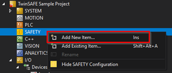
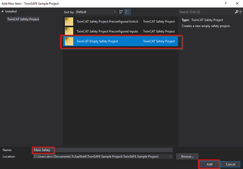
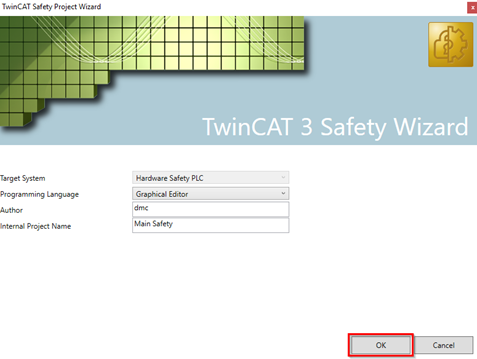
Start by right-clicking on the “SAFETY” section in your project and selecting “Add New Item…”. From the resulting wizard, I will select “TwinCAT Empty Safety Project” and choose an appropriate name for the project.
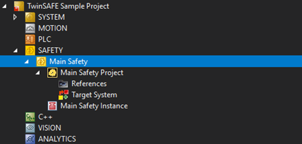
You should now have an empty safety project like so:
2. Creating TwinSAFE Groups
Background
A TwinSAFE project is composed of a set of TwinSAFE Groups that each operate independently of one another. Each TwinSAFE Group will have an operational status that determines how the group’s outputs are set.
It is important to understand the fail-safe behavior of individual TwinSAFE Groups. When a TwinSAFE Group is not in the “Run” operational state, the group’s outputs will all default to their fail-safe values. Since each group has its own operational state, one group could be in the “Run” state and setting outputs according to its internal logic, while the other group could be in the “Error” state and setting its outputs according to the fail-safe behavior.
The operational state of a TwinSAFE Group can be observed live after the project has been downloaded to a target by monitoring the online data or by mapping the state information to the I/O tree via the group’s properties.
Building Groups
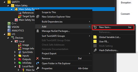
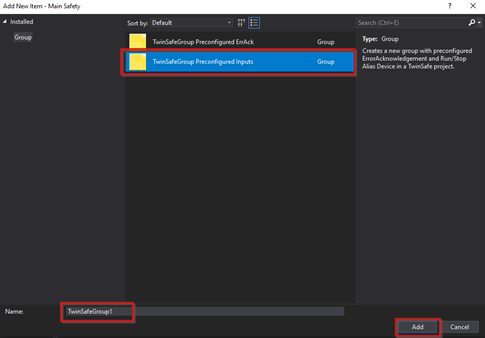
Let's create a TwinSAFE group. Right-click on the safety project and select “Add>New Item…”. Select “TwinSafeGroup Preconfigured Inputs” and give the group an appropriate name. You may notice that this option indicates that it will include preconfigured ErrorAcknowledgement and Run/Stop Alias Devices. These are two inputs into the TwinSAFE Group that will need to be configured later for the group to run once downloaded to the target. See the later section “Run/Stop and ErrorAck Group Variables” for more information on how these are used.
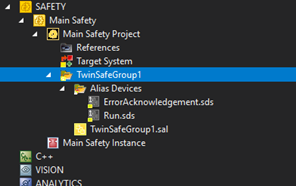
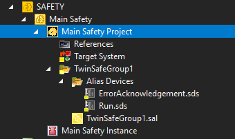
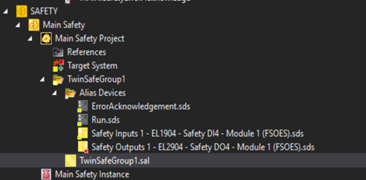
You should now see the TwinSAFE Group appear in your project:
3. Selecting Project Target
The project target indicates the safety controller which you want to download the project to. Some systems may include numerous safety targets. Some drives will contain safety cards internally that projects can be downloaded to. Sometimes, a safety project will be too complex for a single controller to handle, and other times, it just makes more sense to distribute the safety logic to multiple controllers.
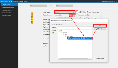
To select the target system for a safety project, double-click on the safety project. From the resulting window, you will need to configure a couple of settings. First, select the type of target system. For this example, I will choose the EL1918 since I have one configured in my IO tree.
Next, select the target select button next to the listed “Physical Device”. A window will pop up that will allow you to select a device matching the type of device you specified in the previous step.
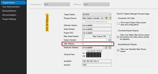
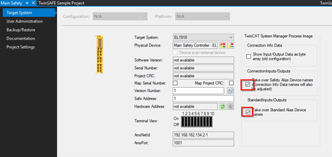
Once the physical device has been selected, confirm that the Safe Address matches that of the physical device. Finally, I suggest that you select the options detailed in the image below. By selecting these options, the project will automatically update the device in the IO tree to match whatever Alias Devices you have configured for communication:
4. Linking Safety Hardware
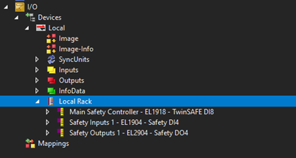
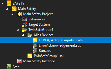
Next, we will link some hardware into the project. When linking hardware signals, we can choose to manually create our “Alias Devices” or import configuration from the IO tree. I have set up some sample hardware in my project to use as an example:
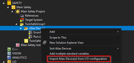
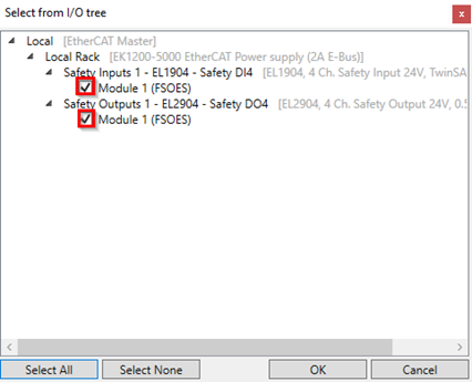
The easiest way to link this hardware is to right-click on the “Alias Devices” in your TwinSAFE Group and select “Import Alias-Devices(s) from I/O-configuration”. The resulting wizard will allow you to select which devices to import:
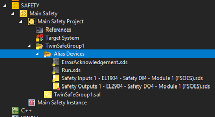
After the import, your Alias Devices should include the devices you selected:
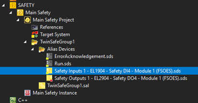
If you are performing this import offline, you may have received a notification that the addresses could not be found. Regardless, you should double-click on each of the new connections and verify that the FSoE Address matches the configuration of the dip switches on the hardware:
Configuring Locally Aliased Device
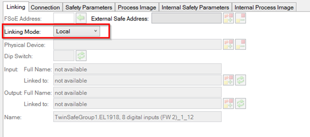
Certain target systems, such as the EL1918 card, have onboard IO that will need to be linked. These devices may not appear in the “Import Alias-Devices(s) from I/O-configuration” wizard. You will have to configure this device manually. Follow the instructions in the next section to add the Alias Device of the correct type, then change the “Linking Mode” to “Local” instead of “Automatic”:
Configuring Alias Devices Manually
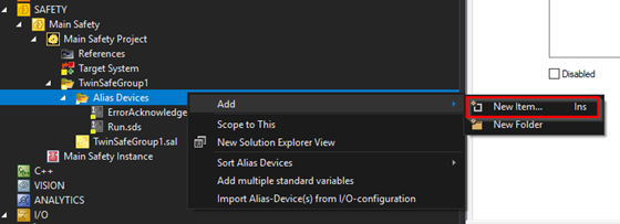
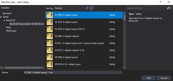
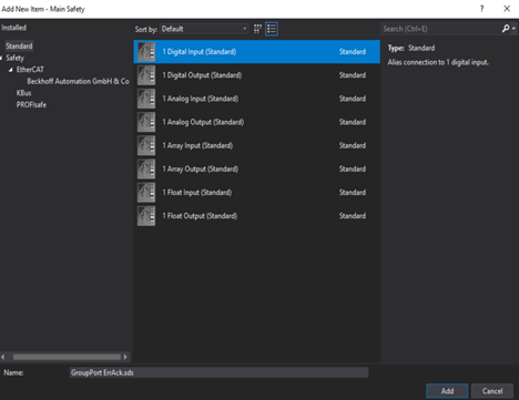
The alternative to using the “Import Alias-Devices(s) from I/O-configuration” option is to add each alias manually. Right-click on “Alias Devices” and select “Add>New Item…”. From the resulting wizard, select the type of device you would like to link. To find the right safety device, you may need to navigate to a specific location in the left navigation pane. Most Beckhoff safety devices will be located under “Safety>EtherCAT>Beckhoff Automation GmbH & Co”.
If you do not see the device you are looking for in the wizard, you may need to delete the Alias Device Templates folder (C:\ProgramData\TwinCAT Safety\AliasDeviceTemplates) and install the most recent version of TE9000. Deleting this folder will clear some cached templates and allow the installer to generate the most up-to-date versions:
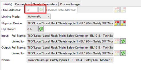
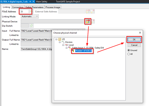
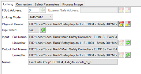
After adding the Alias Device, the physical device needs to be mapped. Double-click on the Alias Device and navigate to the “Linking” tab. From here, set the FSoE Address to match the dip switch configuration on the physical device, then select the target for the physical device using the window that appears after pressing the “Select Target” button. After you save the changes, you will see the input and output linkings update automatically:
A Note About Process Images
In the Alias Device, you may notice the “Process Image” tab. The process image describes the layout of data that is being passed to/from the physical device. For the TwinSAFE Group to run, the Process Image of the Alias Device needs to match the configuration on the physical device:
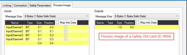
From this view, the name of each of the inputs can be configured to make the TwinSAFE Group logic more readable.
5. Configuring Group Ports
Each TwinSAFE group has its own set of Group Ports. Group Ports provides status and control of the TwinSAFE Group. While most of these Group Ports are optional, every TwinSAFE Group will need to have both the “Run/Stop” and the “Err Ack” ports configured.
When the safety controller is first powered on, no TwinSAFE Group will be running. All TwinSAFE Groups will boot into a safe state, outputting all fail-safe values. In order to trigger the safety logic and write outputs accordingly, the TwinSAFE Group requires a high signal (1) to be written to the “Run/Stop” Group Port. As long as this is held high and there are no errors within the system, then the TwinSAFE Group will run according to its logic.
If the TwinSAFE Group were to error out, then it would enter an ERROR state and not return to its normal behavior until the “Err Ack” Group Port sees a rising edge. After this has been signaled (and the “Run/Stop” Group Port is still high), the TwinSAFE Group will restart and enter RUN Mode.
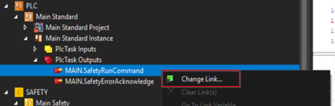
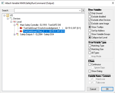
For this example, I have a simple PLC project with logic to write to these Group Ports. Link the outputs from the PLC project instance to the corresponding standard outputs on the safety controller that is the target for the safety project from the Solution Explorer:
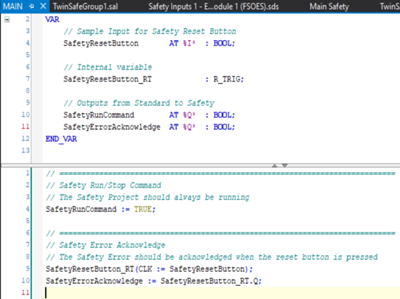
Configuring the Group Ports Manually
If you are working with an existing project and do not have the autoconfigured group ports, we need to add standard Alias Devices to the TwinSAFE Group, connect them as we had above, and then connect the Alias Devices’ data to the Group Ports from the Variable Mapping window. We have not discussed the Variable Mapping window yet, as it will be covered later in this blog post; however, it can be accessed by opening the safety logic for the TwinSAFE Group (.sal file), at which point it will appear in the IDE.
To add the Alias Devices, consult the section “Configuring Alias Devices Manually” and add two “1 Digital Input (Standard)” devices, one for the “Run/Stop” and one for the “Err Ack”. Once they are added, link them as described above.
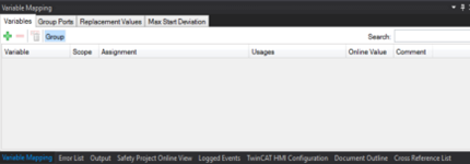
Next, open the safety logic for the TwinSAFE Group by double-clicking on the “.sal” file. Once it is open, look for the Variable Mapping window. The Variable Mapping window may appear elsewhere in the IDE and may be an unfocused tab. Mine appears in the lower center section in the same panel as the Error List and Output windows:
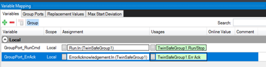
We are going to add two variables to the variable mapping. These variables will take the standard input as their assignment and the Group Port as their usage. This configuration will pass the value of the standard input into the group port.
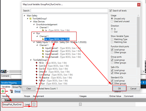
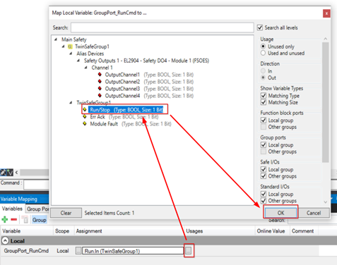
To add the first variable, select the green plus button in the top left. Name your variable with a name along the lines of “GroupPort_RunCmd”. Select the ellipses button for the Assignment cell and select the proper Alias Device input for the run command. Select the ellipses button for the Usages cell and select the “RunStop” Group Port input:
Repeat these steps for the “Err Ack” Group Port:
Conclusion
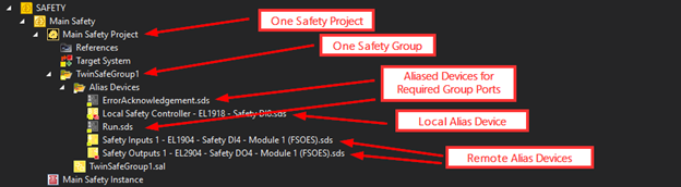
At this point, you should have a Safety Project with the following:
- Safety Project
- TwinSAFE Group
- Standard Alias Devices Configured to connect to Group Ports
- Safety Alias Devices
- Local Device Alias
- Remote Devices Aliases
Now that the safety project is set up, you are ready to get programming.
Want help getting your safety system up and running? Ready to take your Automation project to the next level? Contact us today to learn more about our solutions and how we can help you achieve your goals.