This is Part 3 of Getting Started with XTS. The first two posts in the series discuss Beckhoff XTS, walks through the installation process, setting up a base project, and configuring an XTS system. Today we will continue by setting up an XTS simulation and begin adding logic into our application
Beckhoff XTS Series
Part 1 - Downloads and Starter Project
Part 2 - Setting Up a Physical XTS System
Setting Up an XTS Simulation
Start the XTS Simulator
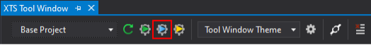
XTS has a built-in simulator that you can start through the XTS simulation builder. This is the gear icon with a blue arrow.
Start the XTS Simulation Builder
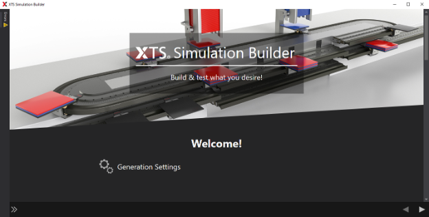
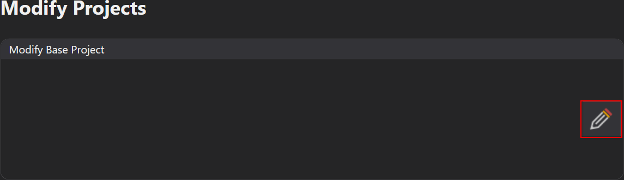
This starts the XTS simulation builder. You can select from a few template projects, but modifying the base project will give you the most control over the XTS system being set up. To do this, click the pencil next to modify base project.
Configure XTS Modules
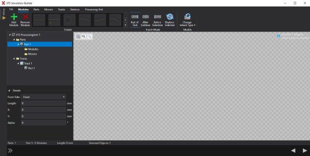
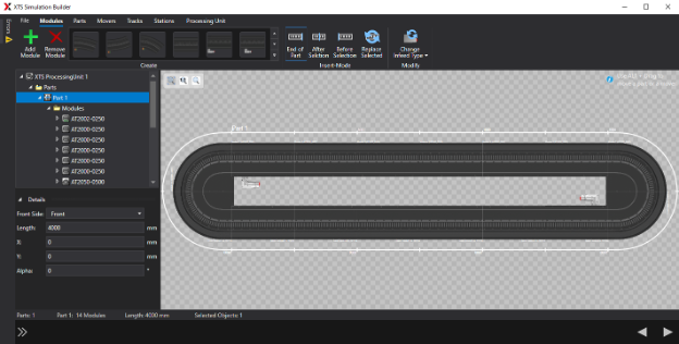
The first tab of the simulation builder is to configure the modules. Here you can add XTS track modules to build your track. In the top bar, you can select from the catalog of XTS modules and hovering over each module will give you the part number. To add a module, either select the module and click the add module plus button or double click on the module.
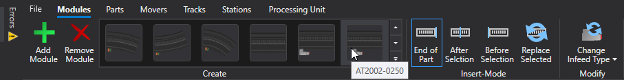
The last four digits of each module’s part number represent its length in millimeters. There are some modules that look the same but have different lengths, so be sure to select the correct length of each part for your application. Below is a simulation track for the XTS larger starter kit. It uses two AT2002-0250, 2 AT2050-0250, and 10 AT2000-0250 modules to form a 4m loop.
Configure XTS Movers
Next, navigate to the Movers tab.
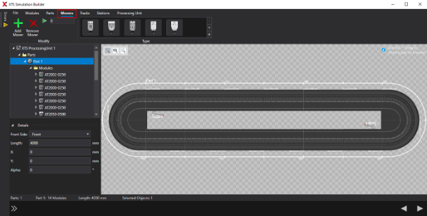
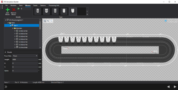
Here you can add movers to the XTS track. Similar to the modules, at the top you can select which mover from the Beckhoff XTS catalog you’d like to add to the track. To add a mover, select the type and then click the add mover plus button. Below are the simulation movers for the XTS large starter kit. It uses 10 AT9014-0070 movers.
Configure Parts, Tracks, and Stations
For this example, we’re not going to be using any parts, tracks, or stations. Here’s a quick rundown of what each of them are with links to the Beckhoff documentation for more detail.
- Parts – Groupings of modules. Since our large starter kit is a loop, we only have the one part which was added by default.
- Tracks – A route that can be used by movers that is made up of one or multiple parts. Since our large starter kit is a loop with only one part, we also only use the single default track.
- Stations – A station in this configurator is still in the beta phase and is currently purely cosmetic. Stations will display in the XTS tool window, but the movers cannot use these stations in their logic. We will set up stations in the PLC logic later, so we don’t have to set any up here.
Configure XTS Real-Time Settings
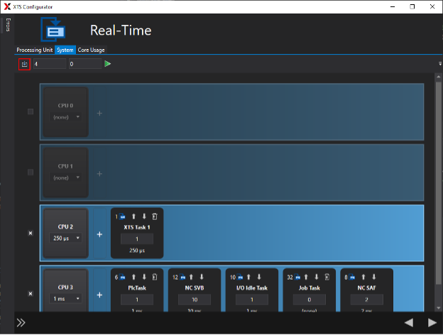
Lastly, we need to set the real-time settings for the XTS system. This is functionally the same as going to SYSTEM > Real-Time, but it’s conveniently here in the configurator as well. First, navigate to the System tab and click the download button to sync the number of cores on your target to the configurator.
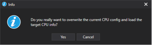
Say "yes" to the popup that asks if you want to overwrite the current CPU config.
The XTS Task 1 has to be configured onto an isolated CPU by itself with a 250μs base time and 1 cycle tick. Isolated cores are represented by an orange rectangle on the right side of the core. You can select which cores are being used with the checkbox on the left side and move tasks around using the up and down arrows on each task. The remaining tasks on the system can be set up to fit your system's needs, but the XTS Task 1 should be configured like the image below.
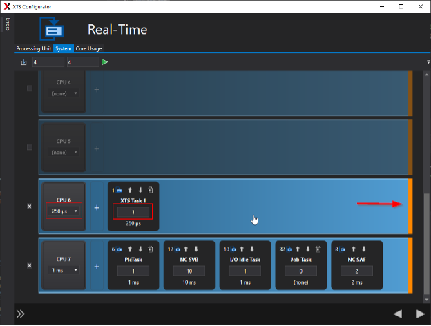
If you’re simulating on your engineering computer, keep in mind that all tasks must be on isolated cores, not just the XTS Task 1. The image above has all tasks on isolated cores for this reason.
Finish the XTS Simulation Builder
Click the next button a couple times and the XTS simulation builder should process the information to add the XTS system to your solution. This may take a few minutes, but afterwards the simulation builder should close. To start sending movers around the track, go to step 5.
Adding Logic to the XTS System
This section assumes that you’re using the XTS_Base code provided on Beckhoff’s GitHub. It’s highly recommended to use this since it provides well-tested code for commonly used XTS tools like movers, stations, zones, position triggers, etc.
Check IdDetectionMode
Under SYSTEM > TcCOM Object > XTS ProcessingUnit 1, go to the Parameter (Init) tab. Under the section for Mover ID Detection, we will want to set IdDetectionMode to the correct detection mode for our system.
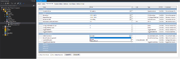
If you’re simulating an XTS system, the IdDetectionMode should be set to Standard. If you’re working with a physical XTS system, then it depends on your movers. Some movers are identified with mover 1 magnet plates. If you have no mover 1 magnet plates, set IdDetectionMode to Standard. With one mover 1 magnet plate, set the IdDetectionMode to Mover1. With multiple mover 1 magnet plates, set the IdDetectionMode to MultipleMover1.
Setting the GVL Parameters
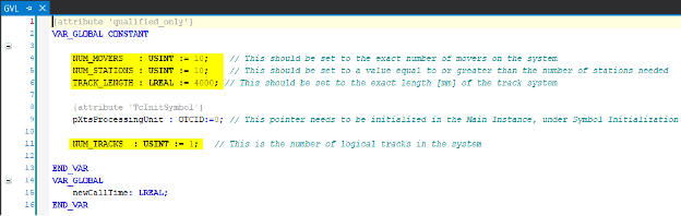
Under the Main Project, open GVLs > GVL. In this global variable list, you’ll need to set the following variables
- NUM_MOVERS – This should be the number of movers in your XTS system. In our case, 10.
- NUM_STATIONS – This should be set to a number greater than or equal to the number of stations you’ll add to your system. In our case, we will keep it at 10.
- TRACK_LENGTH – This should be the length of the track in your XTS system in millimeters. In our case, 4000mm. If you don’t know the track length, you can find it under SYSTEM > TcCOM Object > XTS ProcessingUnit 1 > Track 1 in the Parameter (Online) tab. The Length parameter should show an online value which should be entered for TRACK_LENGTH.
- NUM_TRACKS – This should be set to the number of tracks in your system. In our case, 1.
Update the Track OTCID in MAIN
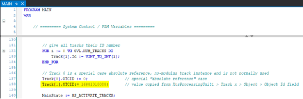
In the MAIN program inside the POUs folder, on line 138 there is an assignment to Track[1].OTCID. This will likely need to be changed.
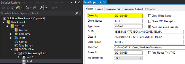
You can find your track’s OTCID under SYSTEM > TcCOM Objects > XTS ProcessingUnit 1 > Track 1 in the Object tab.
You can then copy this value and assign it to Track[1].OTCID in MAIN. Make sure to change the “0x” prefix to a “16#” to match structured text formatting for hexadecimal numbers.
Link the Mover Axes
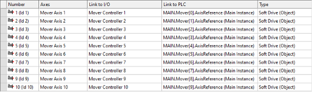
Rebuild the solution first by going to the top toolbar and selecting Build > Rebuild Solution. This makes sure that our change to NUM_MOVERS regenerated the correct number of AXIS_REFs to link to. After rebuilding, go to MOTION > NC SAF > Axes and you’ll see a list of axes that are in our solution. They should already be linked to their I/O components, which should be Mover Controllers. The next step is to link them to their PLC AXIS_REFs. Select all the axes using Shift + Click, then right click to select Change Axis PLC Links.
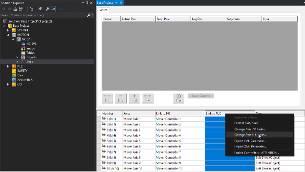
You should see the mover axis references show up. Click each reference to link all the movers to their NC axes. The linking should look like the image below afterwards.
Run the Program
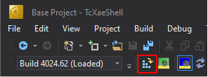
We can now activate our configuration. Do this by clicking the icon shown below.
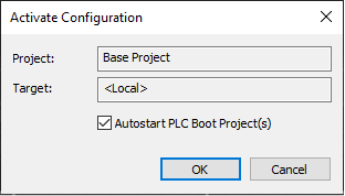
Click OK in the next popup.
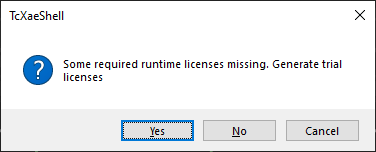
If you haven’t already purchased licenses from Beckhoff, you’ll likely get a popup asking if you want to activate trial licenses. Click yes and follow the steps to get a free 7-day trial license. Once you deploy the code onto a production machine, make sure to get a license from your local Beckhoff sales representative.
After activating configuration, the target device should switch into run mode, which is indicated by the green gear icon next to the activate configuration button being highlighted instead of the blue one. Once in run mode, we can enable and start the movers.
Start the Movers
The solution we pulled from the Beckhoff GitHub already has a simple HMI to get the movers started. Let’s log in by clicking the green door with the arrow pointing towards it.

After logging in, open the visualization under Main Project > VISUs > Controls.
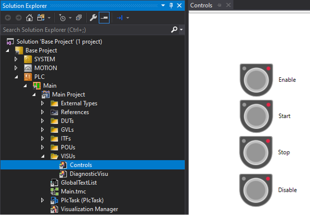
This provides four buttons for interacting with the XTS system.
- Enable – Will run the enable sequence for the movers, which initializes their order and assigns movers to tracks.
- Start – Once the movers are enabled, this will start running the station logic for the movers,
- Stop – This will stop the movers but will keep them enabled.
- Disable – This will remove the movers from their tracks, which allows for errors to be reset. If your track is mounted vertically, it’s worth noting that this will depower the movers and they will succumb to gravity.
Click the enable button. Then click the start button. If you have a physical XTS system, you should see the movers start to move. Both physical and simulation systems can take advantage of the XTS tool window to see a live view of the track.
Live Monitor the XTS Track
Go back to the XTS tool window. You should be able to click the live view button to see the current state of the movers on the XTS track.
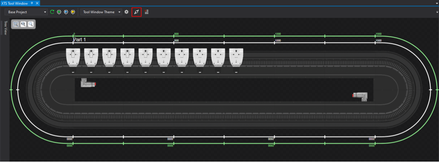 At this point, you should see the movers going around the track according to the station logic that was already in the code we downloaded from Beckhoff’s GitHub.
This should help get your physical or simulated XTS system moving. However, all XTS systems are different and this default station logic likely isn’t going to work for your application. Next time, we will explore how to set up stations, position triggers, zones, and other things that can help customize the XTS system further.
Beckhoff XTS Series
Part 1 - Downloads and Starter Project
Part 2 - Setting Up a Physical XTS System
If you’d like help with the next steps for your XTS system, DMC is proud to be a Beckhoff System Integrator and has worked on multiple XTS projects and applications. Learn more about our Beckhoff partnership and contact us for your next project.