Using a Switch Matrix for Automated Testing
In the world of Test & Measurement Automation, a turnkey test system may have tens, hundreds, or even thousands of individual signals or signal pairs that need to be verified during a test. Switching and multiplexing are common ways to change a system's hardware configuration by routing signals between the device under test (DUT) and a measurement device, power source, or other signal types to perform automated tests without having to manually disconnect or reconnect signals.
What is a Switch Matrix?
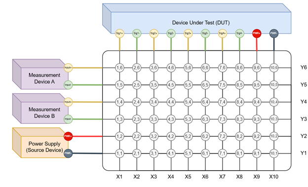
A switch matrix is a controllable hardware module that is comprised of switches organized into rows and columns that form a node or cross-point where each x-line (column) and y-line (row) meet. A switch matrix follows the matrix schematic, as described by documentation from National Instruments. A sketch of a 10x6 switch matrix is shown below:
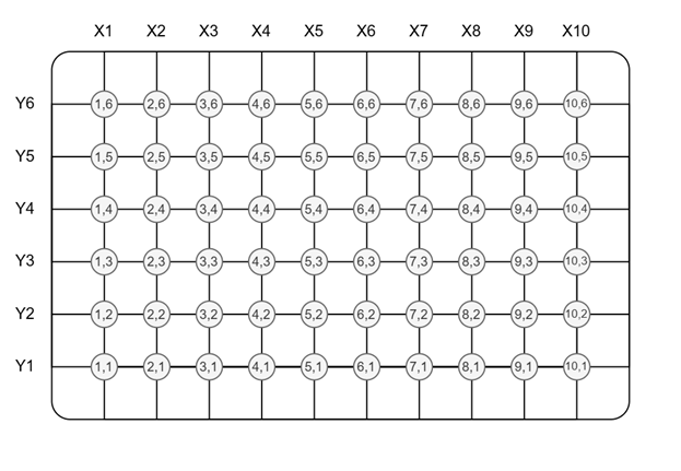
This 10x6 matrix gives a total of 60 “cross-points.” Each cross-point is an intersection between an x-line and y-line. These cross-points can be energized to connect an x-line to a y-line or x-lines to other x-lines. This example shows a 10x6 matrix, however, switch matrices come in many different varieties and sizes.
For example, Pickering Interfaces offers PXI(e) / LXI / PCI matrices that vary by electrical ratings (current and voltage ratings) and number of crosspoints. To get a sense of the scale, a single high-density matrix can have more than 1,000 x-lines with over 4,000 cross-points! When specifying a switch matrix for your application, it is important to have a clear understanding of the maximum number of signals a system may need for a given test system along with the system's electrical characteristics and requirements. There are even specialized switch matrices for high-current, high-voltage, and radio frequency (RF) signal types.
Below we will explore the fundamentals of a switch matrix and how they can be used in an example automated test system:
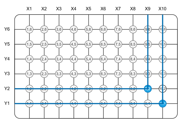
Connecting X-lines to Y-lines
For example, energizing nodes (9,2) and (10,1) will create a connection between X9 and Y2, and another connection between X10 and Y1.
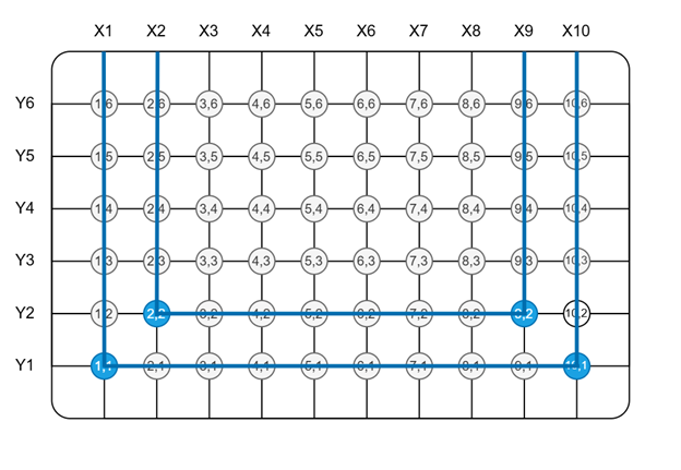
Connecting X-lines to X-lines
Similarly, energizing nodes (1,1), (2,2), (9,2), and (10,1) will create a connection between X1 and X10, and another connection between X2 and X9.
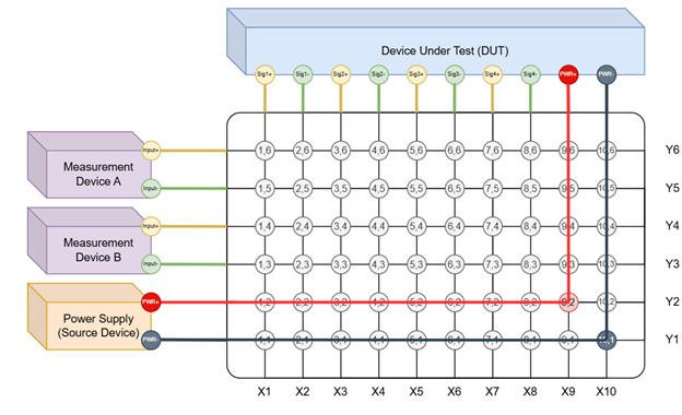
Example Test System Hardware
Consider a DUT that has four data signal outputs and one power input. The test sequence required for this system is as follows:
- Step 1: Connect DUT to power source.
- Step 2a: Measure DUT Signal 1 with Measurement Device A.
- Step 2b: Measure DUT Signal 2 with Measurement Device B.
- Step 3a: Measure DUT Signal 3 with Measurement Device A.
- Step 3b: Measure DUT Signal 4 with Measurement Device B.
- Step 4: Disconnect DUT from power source.
A test system that is capable of performing these steps may look something like this:

Where each of the required hardware connection steps are shown below:
Step 1 – Connect Device Under Test (DUT) to a Power Source
- Connect the DUT to the power source by energizing relays (9,2) and (10,1).
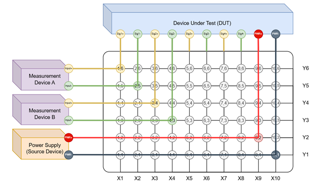
Step 2 – Measure DUT Signal 1 and Signal 2
- Connect Measurement Device A to Signal 1 by energizing relays (1,6) and (2,5).
- Connect Measurement Device B to Signal 2 by energizing relays (3,4) and (4,3).
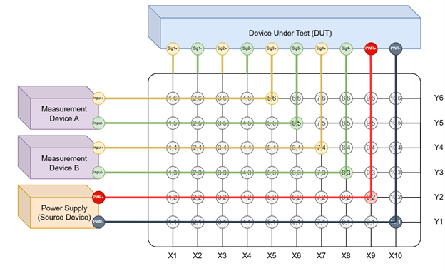
Step 3 - Measure DUT Signal 3 and Signal 4
- Disconnect Measurement Device A from Signal 1 by deenergizing relays (1,6) and (2,5).
- Disconnect Measurement Device B from Signal 2 by deenergizing relays (3,4) and (4,3).
- Connect Measurement Device A to Signal 1 by energizing relays (5,6) and (6,5).
- Connect Measurement Device B to Signal 2 by energizing relays (7,4) and (8,3).
Step 4 - Disconnect DUT from Power Source
The example above illustrates how a switch matrix can be used to measure multiple signals with a single measurement device. This example uses Measurement Device A to measure DUT Signal 1 and Signal 3; Measurement Device B measures DUT Signal 2 and Signal 4. This example could be modified in several ways to configure the test system for different requirements.
For many applications, all measurement devices and DUT signals are connected to x-lines to reduce the number of y-lines which reduces the number of cross-points and overall hardware complexity. It is always important to read the switch matrix’s user manual to understand any restrictions the specific matrix may have. For example, many switch matrices do not support connecting multiple y-lines to a single x-line.
Why use a Switch Matrix?
A switch matrix is used in a test system to connect and disconnect multiple devices to and from each other automatically, often during a test sequence. For complex automated test equipment (ATE) racks that utilize multiple test devices and high signal count, a switch matrix can help minimize cycle time and eliminate manual setup that would otherwise require an operator. In cases with extremely high signal counts, a switch matrix transforms the impossible into the possible!
Conclusion
A switch matrix is a versatile piece of hardware that can help maximize an automated test equipment's (ATE) efficiency by changing the hardware configuration during an automated test. If a test workflow has a high signal count and requires manually connecting and disconnecting signals as part of the test, consider employing a switch matrix as part of your test system.
For examples of case-studies which use a switch matrix, check out the links below:
Ready to take your Test & Measurement Automation project to the next level? Contact us today to learn more about our solutions and how we can help you achieve your goals.