ARM Cortex-M processors are popular choices for embedded applications, and the ability to easily update the code running in these devices without specialized equipment can be an invaluable asset. To achieve this, it’s common practice to use a bootloader, a specialized program which typically runs before the main application and has the capability to overwrite it. If a device becomes corrupted or new functionality is needed, it can be updated in the field, and if the update is interrupted or firmware which doesn’t work properly is loaded, the bootloader can be used to update the device again and restore functionality.
This blog will cover the basic components of bootloader implementation—memory layout, in-app programming, and launching the app from the bootloader—using the STM32F779, a Cortex-M7 part, as an example.
Controlling Memory Layout
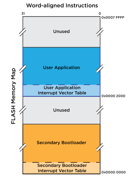
The first challenge to solve is placing both the bootloader and the main program within the flash memory of the device. Microcontrollers typically contain a primary (built-in) bootloader that will always execute first and then jump to a certain location in flash memory. As such, for the custom bootloader to run before the main app, it should be placed in the first location where the chip looks, and the main application should be placed at a higher address.
This doesn’t require any extra effort when setting up the bootloader but will require some changes when building the main application. Once a program has been converted to binary form, it typically needs to be located at a specific address to function correctly. This location information is baked into the binary during the linking step, so to change this, you’ll need to modify the linker script. The simplest approach is building the bootloader and main application completely separately so each has its own linker script. In this case, only small tweaks from the IDE/manufacturer provided script will be needed.
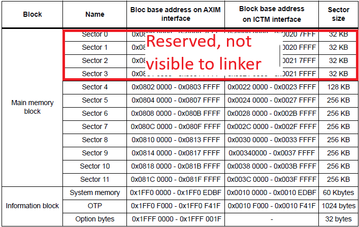
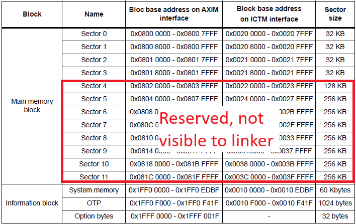
For the STM32F779AI, this can be done by changing the base address and length of the ‘FLASH’ section for each program so the linker won’t place anything in the region reserved for the other program.
Main application linker file:
{
  RAM (xrw) : ORIGIN = 0x20000000, LENGTH = 512K
  FLASH (rx) : ORIGIN = 0x08020000, LENGTH = 1920K
}
Bootloader linker file:
{
  FLASH (rx) : ORIGIN = 0x08000000,   LENGTH = 128K
}
Adding Support for Firmware Updates
Now that the bootloader and main application are in place, the next step is giving the bootloader the ability to update the main application. There are any number of ways to supply new firmware to replace the main application, so we’ll move past this and assume that the bootloader already has access to a new binary.
Regardless of whether it’s stored on a connected USB flash drive, being sent byte by byte over UART, or retrieved from any other source, once the device has the firmware file, the next step is to write it over the main program area. Most embedded devices have support for some form of IAP (In Application Programming) functionality which allows a device to write to its own flash memory while running, though it will be named and implemented differently from chip to chip.
On the STM32F779, for example, IAP is accomplished through a flash controller peripheral, but the chip’s HAL (hardware abstraction layer) provides functions to manage this peripheral, so a developer can just call “HAL_FLASHEx_Erase” and “HAL_FLASH_Program” (and some supporting functions) with the data to write and the addresses to erase and write over.
Launching the Main Application
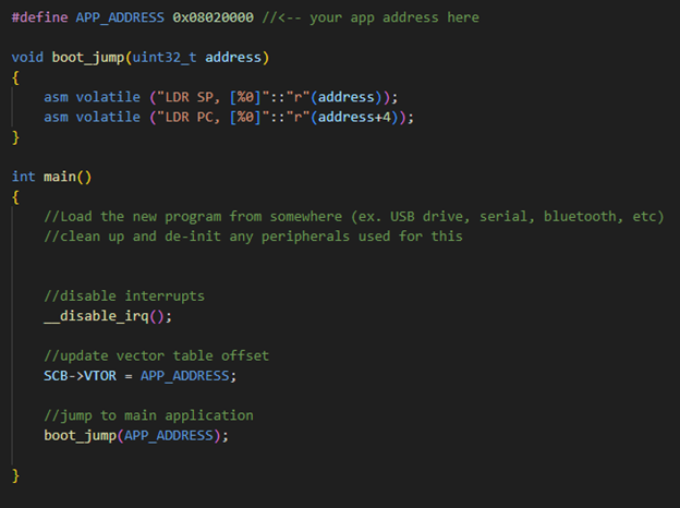
Once the new program has been saved, all that’s left is to run it. There are a few steps to doing this safely, and I’ll cover them in execution order. First, interrupts need to be disabled. The exact implementation will vary between chips, but most will have a simple way to do this. On the STM32F779AI, ST’s HAL provides the following function for this purpose:
__disable_irq();
Disabling interrupts is necessary because the next step is to swap to the new vector table. The vector table is a chunk of memory which contains critical information for the program to execute, mostly pointers to interrupt handlers. There are different ways to do this depending on architecture; the STM32F779AI is built on the Armv8-m architecture, which includes a vector table offset register (VTOR) for this purpose, and the ST’s HAL exposes it as a structure that can be written as follows:
SCB->VTOR = APP_ADDRESS; //chip will now look at main application’s vector table when handling interrupts
Finally, jumping execution to a different program requires accessing the core’s registers to change the program counter, a value which indicates the location of the next instruction to run, and the stack pointer, which indicates where temporary information is stored.
For chips using the armv8-m architecture, the first word of the binary is the initial location of the stack, and the second word is the address of the reset handler. Loading these into the stack pointer and program counter will cause execution to continue from the new program as if it had initially booted there. This can be done directly with inline assembly instructions, demonstrated below.
void boot_jump (uint32_t address)
{
  //set the stack pointer to the initial stack location, pointed to by the data at ‘address’
  asm volatile ("LDR SP, [%0]" :: “r” (address));
  //set the program counter to the reset handler pointed to by the data at ‘address’+4
  asm volatile ("LDR PC, [%0]" :: “r” (address+4);
}
From here, the main application should run normally. Be sure to turn interrupts back on, since they wouldn’t normally be disabled on startup.
With that, the basic functionality of a bootloader is complete, and additional features like encryption or a user interface can be added to suit a variety of needs
Included below is a code summary of the elements discussed, and how they’re implemented on the STM32F779AI.
Ready to take your embedded project to the next level? Contact us today to learn more about our solutions and how we can help you achieve your goals.