As an Ignition Premier Integrator, DMC works on dozens of SCADA projects every year for clients across a wide range of industries.
As plants expand and grow, we are frequently asked to integrate more and more devices. Luckily, Ignition has pre-made OPC UA device drivers for many of the most widely used PLCs such as Siemens and Allen Bradley processors that are OPC UA ready. Yet there are still several—both new and legacy—that rely on common protocols like Modbus TCP.
In this blog, I will walk you through setting up and using Ignition’s OPC UA Modbus TCP Driver, as well as how to configure an Address Map to allow OPC tags to be browsable.
Adding the Device to the Ignition Gateway
Assuming the IP Address is set and known for the Modbus TCP device, and it is properly networked to the Ignition gateway, we can begin to configure the Modbus TCP driver through Address Mapping.
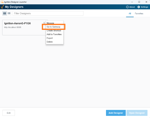
Navigate to the Gateway Webpage (Use a web browser or navigate to the webpage through the Designer Launcher).
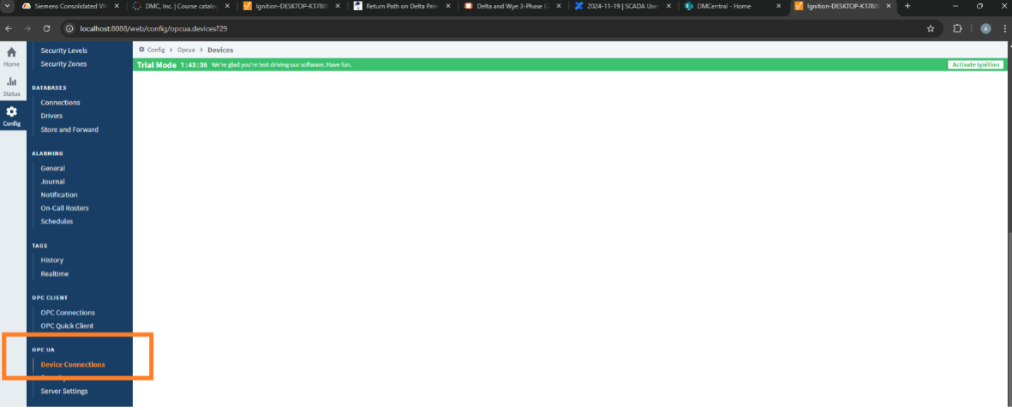
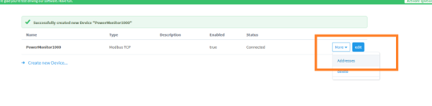
Once inside the Ignition Gateway, go to “Config” à “OPC UA” à “Device Connections” and select “Create new device.”

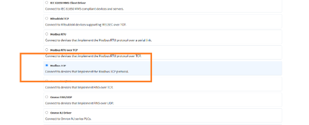
Select the “Modbus TCP” driver and click “Next >” at the bottom of the screen .
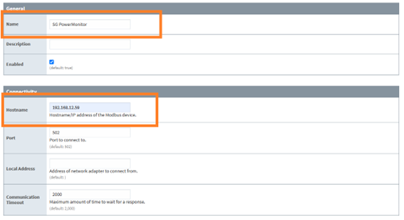
Give the device a name and add the new IP address (The default port is 502).
Adding an Address Map
After creating the Modbus TCP device, go to “More” à “Addresses” to add the data requests with Ignition’s Modbus Address Map. By creating a Map developers can avoid setting up each Ignition tag on a case-by-case basis by pointing at a Modbus register, grouping Modbus registers in common blocks, and customizing the naming or number scheme of Modbus blocks (Inductive Automation Docs, Modbus Address Mapping).
Now go to the device’s manual, which should display the Modbus Registry addresses for your desired tags. The following screenshots are an example from the manual for an Allen-Bradley PowerMonitor1408-EM3A-ENT.
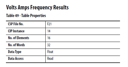
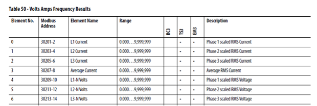
From these tables we will need the “Data Type” and “Modbus Address” to configure the Modbus addresses you are interested in. The Ignition table is pictured below (Click “Add Row” at the bottom of the screen to add an address).
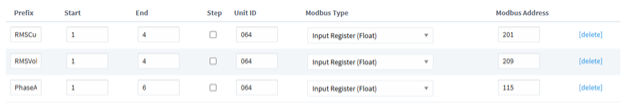
“Prefix” will name the group of addresses that you are pulling.
“Modbus type” and “Modbus Address” will correspond to the Modbus address from the manual. “Input Register” signifies addresses in the “3XXXX” range, “(Float)’ signifies the data type and the Modbus Address selects the specific point. The table below shows Modbus register prefixes based on data type.
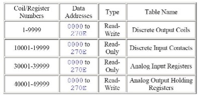
“Unit ID” is the Modbus Address of the device (The default is 64 in this case but can also be found in the devices manual).
“Start” and “End” give the range of data points to pull. “Start” can be any number you want and will only affect the naming convention of the tag within the gateway (The actual Modbus start address is decided by “Modbus Address”). The range between “Start” and “End” will determine how many tags are pulled. This will pull the number of bytes necessary for the datatype. (Ex “Start” = 1 and “End” = 3 for an input register with type “float” at address 201 will pull 201-2, 203-4, and 205-6. “Start” = 0 and “End” = 2 will pull the same addresses but will concatenate 0-2 instead of 1-3 to the Prefix for each tag name).
NOTE: If multiple devices are added to the same gateway, the new address will need to be added to EACH INSTANCE of the device. This can be done quickly through the Import/Export Configuration feature.
Adding tags to the Ignition Designer
You can add tags to the Designer by either creating a tag directly or creating a UDT for the device. This example uses UDTs for ease of replication.
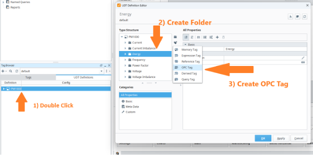
Begin by opening the UDT editor. Double click on the tag as shown below. Then create a folder for the new variable (labeled “Energy” in this example). Within this folder, create an OPC tag.
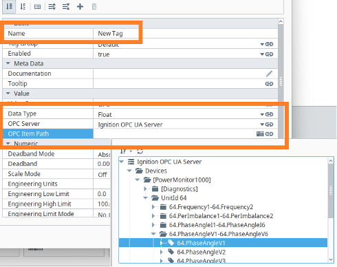
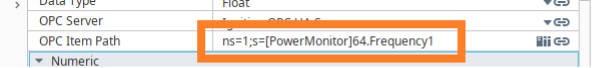
Add the Name, Data Type, OPC Server, and OPC Item Path (Browse for the path with the PLC icon on the right).
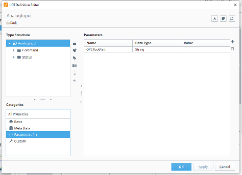
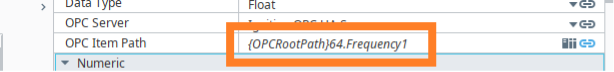
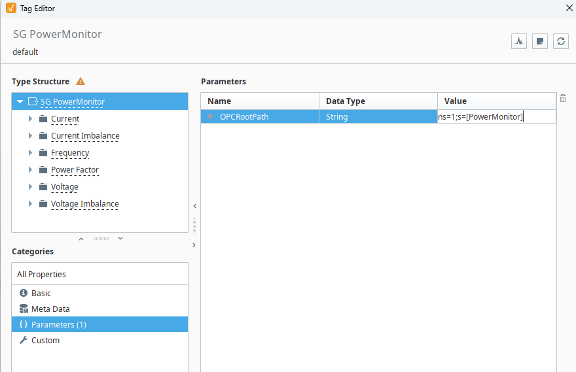
Optionally, to make the path dynamic (for use of multiple devices) create a parameter called “OPCRootPath”. Then replace the first half of the “OPC Item Path” with {OPCRootPath} as shown. This will reflect the dynamic path specified in the instance’s “OPCRootPath” Parameter.
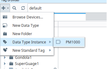
Now create a tag instance (Tags Tab à “+” à ”Data Type Instance” à **UDT Name**) and give the tag an appropriate name.
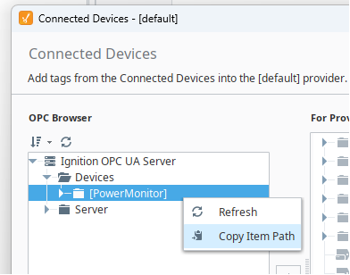
Under the same plus sign as above, go to “Browse Devices…” and find the appropriate device. Right click on the device and select “Copy Item Path."
Then, select your new tag instance of the PM1000, and go to the “Parameters” tab. Copy the OPC item path into the OPCRootPath Parameter.
Now the tags should be loaded into the designer as expected!
Learn more about DMC’s Ignition programming expertise and contact us today for your next project.