The ability to simulate hardware is an invaluable tool to keep in your development kit. It allows you to develop remotely, test changes without interrupting critical systems, and more. This blog serves as an addendum to Nikhil Holay’s informative blog 5 Tips For Getting Started In PLCSIM Advanced.
Simulating OPC UA Communication
If you’re looking to develop a TIA Portal Project that uses OPC UA to communicate to external systems, PLCSIM Advanced has your back—just make sure to select a processor in TIA Portal that has an integrated OPC UA server. For an S7-1500 or ET 200SP CPU, you’ll need firmware V2.0 or above (ET 200S series controllers do not support OPC UA). PLCSIM Advanced does not support S7-1200 controllers at the time of publishing.
Changing the version of your virtual controller is even easier than swapping real hardware. In the Devices & Network view, right click on the PLC and select “Change Device.” On the left, Portal will give you a description of the current device, and on the right, you can select a new device and its version from the dropdown menu.
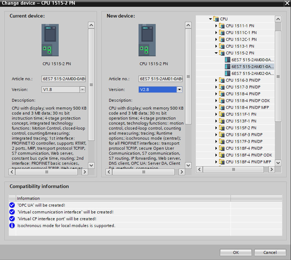
Changing S7-1500 PLC device version in Siemens TIA Portal
How Do I Configure the OPC UA Server Settings?
After creating your device, you must first configure the OPC UA server options in TIA Portal. Access the device Properties, select the General tab and expand the entry for OPC UA, select the Server subtopic and check the box for “Active OPC US Server” in the right panel beneath ‘Accessibility of the Server.’ Leave the remaining settings at their defaults.
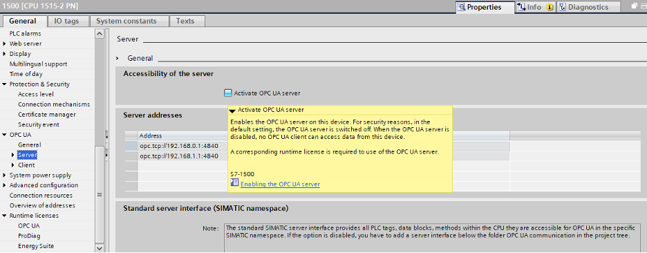
Activating OPC UA server in Siemens TIA Portal
You will also need to select the appropriate license under the Runtime licenses menu.
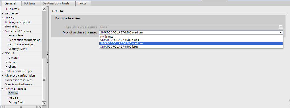
Activating OPC UA license in Siemens TIA Portal
Finally, make sure to configure your PLC’s Access Control settings.
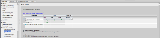
Access control in Siemens TIA Portal
After everything is configured in your project, you’re good to go! Download your project to the PLCSIM Advanced controller you had created previously, as if it were real hardware—see Tip One, Step 3 in Nikhil’s blog.
Configuring PLCSIM Advanced for Cross Platform Testing
One of the great advantages of PLCSIM Advanced is the ability to simulate your TIA Project with external systems—whether that is real hardware (simulating an HMI with a real PLC) or even simulating your PLC with an external SCADA system. For this example, we’re going to demonstrate using OPC UA to connect a simulated Siemens PLC and an Ignition SCADA application.
If you’re planning develop in TIA Portal and Ignition on the same local machine (or VM), use the option for TCP/IP communication with the <Local> network adapter selected. If your Ignition server resides on a different machine or VM, you’ll want to select the network adapter of the machine running PLCSIM.
How does this work on the Ignition side? Thankfully, it’s as straightforward as working with real hardware. On your Ignition server add a new OPC UA Connection, point the Endpoint URL to your virtual PLC, and proceed as usual.
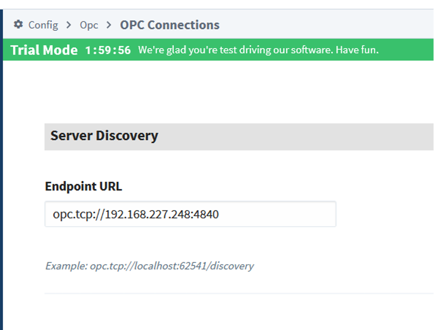
Configuring a new OPC Connection in Inductive Automation Ignition
If the two pieces of software are on the same machine or VM, you should be ready to go. If your Ignition server and PLCSIM are on separate VMs and Ignition indicates there is an issue, you must make sure the two are both set to share the host’s network (via NAT or another method). Check your VM’s Network Adapter settings to be sure.
What About Modbus?
PLCSIM Advanced is also great for testing Modbus communications before arriving at the machine. To do so, you will need a Modbus simulator, such as Modbus Poll, and install it on the same VM (or host machine) as PLCSIM Advanced. For this example, I’ll simply read the first 10 holding registers that I configured on my PLC.
First, I created the MB_SERVER object in my project. A TCON_IP_v4 object is required to configure the Modbus server. You will also want to add a non-optimized DB that will contain your holding registers as well. For a great in-depth discussion of what’s going on with this block, check out Jason Mayes’ blog Using an S7-1200 PLC as a Modbus TCP Slave.
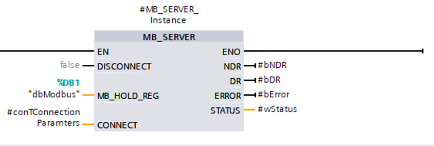
MB_SERVER object in Siemens TIA Portal
In this example, we’ll be communicating over TCP/IP, so set the ConnectionType to 11 and LocalPort to 502.
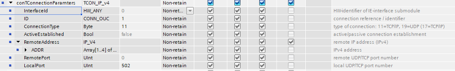
TCON_IP_v4 connection parameters object in Siemens TIA Portal
When you first open a connection in Modbus Poll, you’ll be prompted to configure the connection settings. Enter the IP address of your PLCSIM Advanced controller, the same port you configured in Portal, and verify that you’re using Modbus TCP/IP.
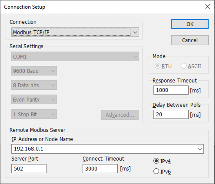
Connection Setup dialog in Modbus Poll
After you click OK, it will return to the main screen where you’ll see a table with 10 entries corresponding to the first 10 holding registers on your Modbus server. If your communication settings are correct, the data in Modbus Poll should match what’s online with your simulated PLC.
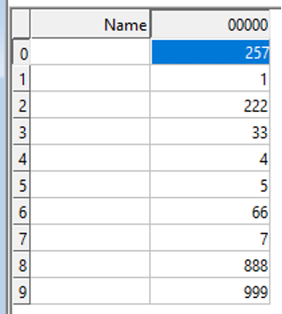
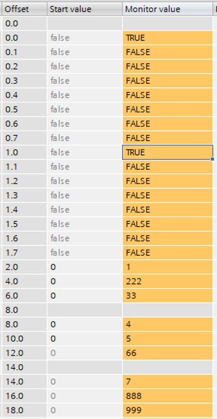
Left: Modbus holding registers in Modbus Poll; Right: Modbus holding registers in Siemens TIA Portal
If you’d like to extend the number of registers, or test something other than Read Holding Registers, navigate to Setup -> Read/Write Definition screen to modify these settings.
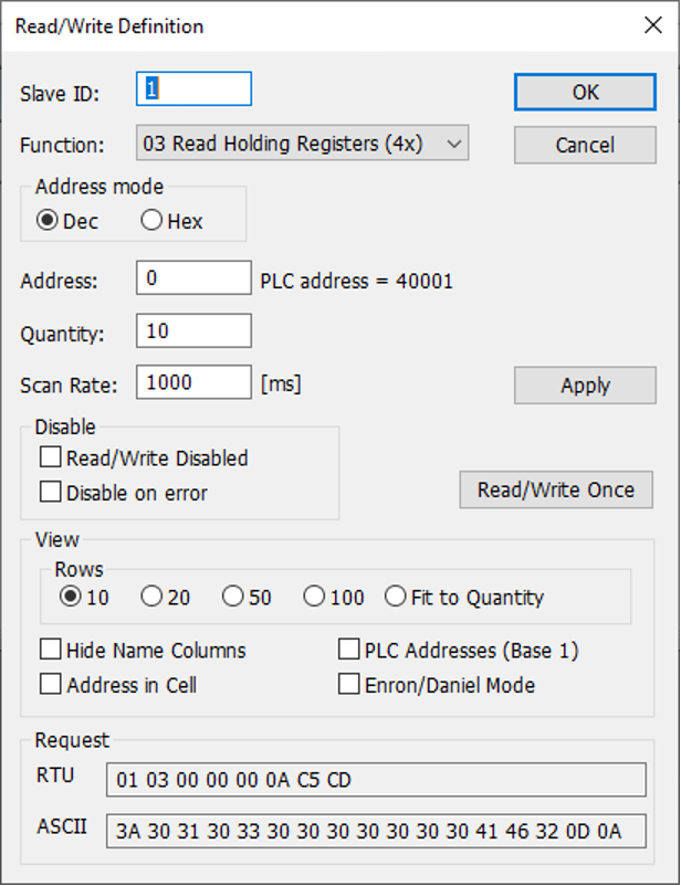
Read/Write Definitions setup menu in Modbus Poll
Conclusion
PLC emulation is a great development tool, and PLCSIM Advanced makes it easy to develop and test your TIA Portal projects with external or third-party systems. It also simplifies testing and debugging Modbus communications without interruptions of service to critical systems.
You can learn more about our Siemens and Ignition expertise, or contact DMC to discuss your next project.