Typically, a MagneMotion track is designed to fit a 2D profile, the track might turn left or right but not up or down. While this is sufficient for most MagneMotion applications, sometimes systems are designed to lift or move MagneMotion track out of its typical 2D plane.
Whether this is to move MagneMotion closer to tooling or to transport MagneMotion vehicles from one level of track to another, configuring this type of track involves careful modifications to the typical MagneMotion system. In this blog we’ll review general guidelines on how to handle these situations.
Note: This blog is for MagneMover Lite systems only. QuickStick systems have a built-in feature of linking and unlinking paths which is a preferred way to handle this issue.
MagneMotion Guide Series
Step 1: Creating the Track Layout
When laying out track, any moving segments of track should be carefully considered. You will need to account for any moving track in your system configuration, but different tracks have different considerations.
Terminus Nodes vs. Relay Nodes
Regardless of how the track is set up it is often a good idea to define any moving track as its own specific path. This allows the host controller to suspend or start that track section independently and makes it much easier to follow if there are any vehicles on the track.
If the track is simple, you can usually add relay nodes to your system to break out your lifting path. In the below example, a single meter of track would be used to raise carriers from a ground section of track to a raised section of track.
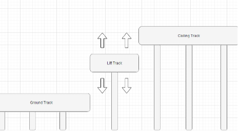

Here, you can maintain a simple track setup. Vehicles can still be sent from the ground track to the lift track or from the lift track to the ceiling track using the same typical motion commands that you’d use in other parts of your MagneMotion System.
However, some tracks are more complicated to set up. Since MagneMotion is constrained to 2D systems any track that requires having multiple motors in the same two-dimensional position will require more a complicated track configuration to set up.
In the example below, the track has been set up with a lift that can move vehicles to any one of three different levels of track.
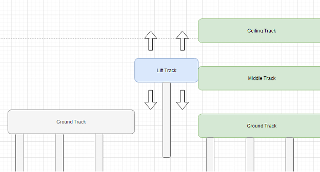
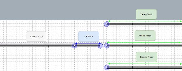
In this example, the track must be configured so that the different levels of track are considered separate from the rest. While regular vehicle commands can still be used to pass vehicles from the left ground track to the lift track, any vehicles sent from the lift track to one of the right-side tracks will need to be done with a terminus node handoff.
Terminus Node Considerations
In general, this terminus node-based configuration should be reserved for tracks where alternate configurations are not possible. While these terminus nodes will function, they come with some additional caveats.
While terminus nodes can be properly simulated, you will need to add additional simulation logic to your PLC to properly run a simulation test of your system. Since MagneMotion will not know that the track on either side of the terminus node spot is next to each other when a vehicle exits through one terminus node it will not automatically appear on the other track section. Spoofing logic will be required to create an additional vehicle to receive it on the other track.
Also, while MagneMotion supports disjointed tracks, many of the MagneMotion tools used in generating files will not work for non-contiguous tracks. For example, the “walk the paths” action will only create a configuration file with the paths of one disjointed section, any additional paths and nodes will need to be added manually. Similarly, the configurator tool cannot generate an .mmrtk file from the configuration of a disjointed track (though you can manually create an .mmtk file on your own using any text editor).
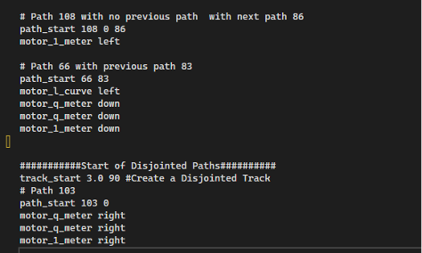
Terminus nodes also require more programming overhead to control and manage. Moving vehicles across a terminus node is more complicated than regular MagneMotion motion commands.
Step 2: Controlling Motion Across Your Lift
Once you have your track laid out, you need to consider how to best control the movement of vehicles across your track.
Having moving track in your system adds another considerable risk to your project. If a vehicle is commanded off the lift track at the wrong time it can fly off the lift into empty air and hurt anyone nearby. While you could theoretically control your lift track the same exact way you control all your other track, it is always a good idea to add some extra precautions when dealing with moving track.
It is also worth noting that MagneMover Lite is not a safety-rated system so including reasonable mechanical constraints in your system is also a good idea. Ideally, any system would be set up so that no matter what, a vehicle wouldn’t fall off the track.
Mechanical Restrictions
Implementing simple solutions like mechanical guarding around your track can help prevent incidents. Alternatively, adding cylinders to the end of a track that actuate to restrict vehicle motion can help ensure system reliability even if power is lost to the MagneMotion track.
There are countless ways to design a system to prevent issues with moving track. It is important to consider the possible failure modes of the system and ensure that they are accounted for in the design.
Traffic Lights
Traffic lights are used in MagneMotion systems to stop vehicles in certain spots of the track. For more information see MagneMotion Blog Part 7: Traffic Lights.
Where moving track is used, it can be useful to keep traffic lights on either side of the track.
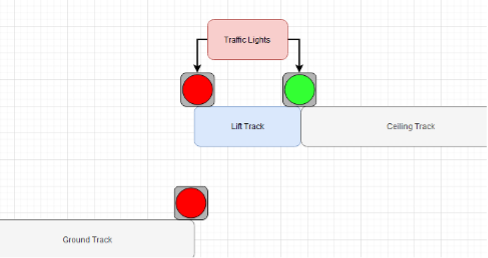
To help ensure that no vehicles are commanded off the end of the track, the lights will be set to turn red when it is not safe for a vehicle to cross.
It is important to note that the traffic light setting is not instantaneous. Not only is there a slight delay in a command for a traffic light being sent from the host controller, but any incoming vehicle will need time to decelerate before the traffic light. This means that when using traffic lights, they should be set to red before the moving track starts to get out of position to ensure there are no issues with incoming vehicles as the track is moving.
Another consideration is that while traffic lights are defined as a single point on a track, they can take up a fair amount of space. When a vehicle is approaching a traffic light it will maintain a distance between itself and the traffic light based on its configured vehicle length.
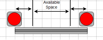
This means that track lifts can run into situations where there is insufficient space to have traffic lights and move vehicles onto the lift track.
Keepout Areas
Another tool MagneMotion has for controlling vehicle flow is the creation of keepout areas.
Keepout areas are configured spots on the track that are set up to make it less likely for vehicles to come to a stop in those spots. When a vehicle approaches a keepout area it will only continue into the area if it has permission to move through the entire area.

This means that vehicles will not get stuck in a keepout area when they’re backed up, but they will still be able to move through them if the track is clear. Similarly, any vehicles in the keepout area when the track suspends will continue moving until they are outside of the area.
Unlike traffic lights, keepout areas cannot simply be turned on and off. They are defined in the MagneMotion configuration file and require updating that file and rebooting the system to change.
Defining Keepout Areas
Keepout areas are defined in the configuration file on a per motor basis. Each keepout area only applies to upstream or downstream motion. If vehicles will be moving across the keepout area from either direction make sure that both are configured correctly.

For setting up a keepout area for moving downstream, the “No Move Permission After” parameters need to be set for each motor in the keepout area. The value should correspond to the distance between the start of the motor and the beginning of the keepout area (a value of 5 meters means this parameter is ignored).
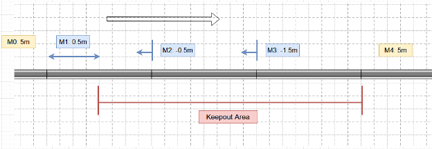
In a keepout area that extends several motors, the first motor in the chain may have a positive value for where the keepout area begins but each motor after it needs to indicate that the keepout area began upstream of it. This means that each downstream keepout area needs to end on the endpoint of a motor.
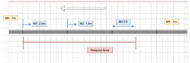
Similarly, for defining keepout areas moving upstream simply reverse this process using the “No Move Permission Before” parameter. Here the value means the distance from the start of the motor to the end of the keepout area (a value of -1m means that the motor is not in a keepout area).
Using Keepout Areas
For the use case of a lift or other moving track, a keepout area can be used to ensure that a vehicle does not stop halfway on the moving track during normal track operation.
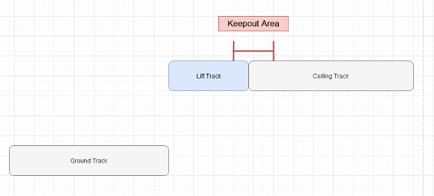
This will reduce the chance of a mechanical failure where the lift tries to move while a vehicle is in the way.
Learn more about DMC's MagneMotion programming expertise and contact us today to get started on your next project.