Traditionally a Beckhoff TwinCAT 3 PLC project would utilize EtherCAT as the primary network protocol for field network devices. In this blog we will review how you can reconfigure additional LAN ports on a TwinCAT IPC to act as an Ethernet I/P master instead. This can be a great option for handling devices more readily available that communicate Ethernet I/P instead of EtherCAT.
Software Requirements
This example will utilize TwinCAT 3 XaeShell and the TF6281 software license for Ethernet I/P Scanner communication.
Task 1: Add Ethernet I/P Device in Project
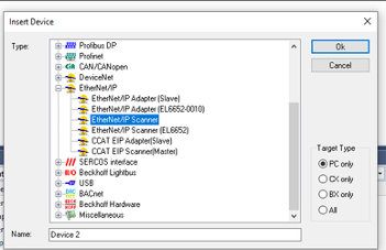
Use the dropdown ‘IO → Devices → Add new item’ and select the Ethernet/IP Scanner option.
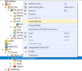
Next, we need to import a new EDS file for our Ethernet I/P field device. Right-click on the newly added EIP Scanner and select the ‘Import EDS File’ option.
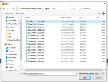
Navigate to the location of the EDS file for your device, then click ‘Open’. This will allow you to select the proper file for your device.
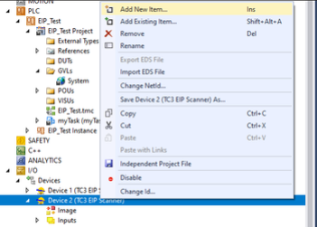
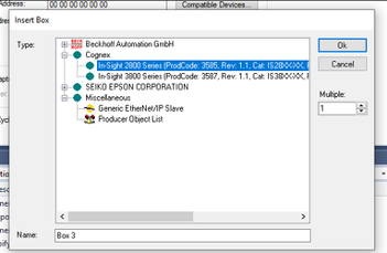
Next, Right-click on the EIP Scanner again and select ‘Add New Item…’. Then select your newly added device from the EDS import. In this example I have added 2 different Cognex Camera models.
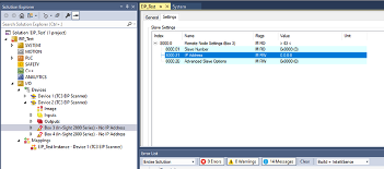
Now, we need to open the added device properties and set the IP address of the device.
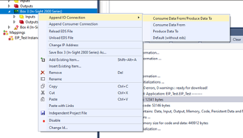
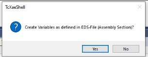
The next step is to append the IO connection. Selecting yes to the popup option below will allow the connection to pull all the pre-configured tags in the EDS file, so that we do not have to individually bit and byte map all the data in the Ethernet I/P communication to the camera.
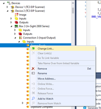
The final step is to link the IO tags to the variable withing the PLC program. Using the ‘Change Link’ option will allow you to search through the configured program variables and assign them to the appropriate IO tag.
Task 2: Configure LAN Port for Ethernet/IP
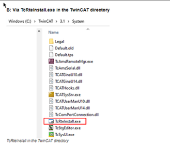
The first step is to install TwinCAT XaeShell on the IPC. With this installation comes the ability to install the Realtime Ethernet Driver to the LAN ports on the IPC. Using the install file from your TwinCAT install at the file path: (C:\TwinCAT\3.1\System\TcRteInstall.exe) you can run this simple application to install the runtime driver. For more information on the runtime driver see this link.
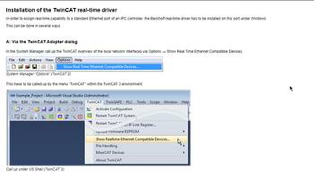
The other option is to Open TwinCAT XaeShell on the IPC. Navigate to the dropdown menu ‘TwinCAT → Show Realtime Ethernet Compatible Devices…’
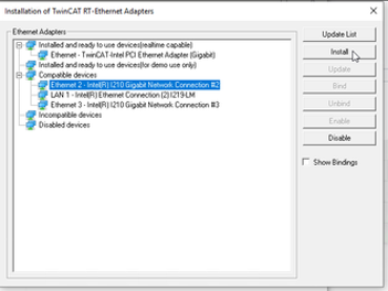
Next, you want to select the proper ethernet port on your IPC under ‘Compatible devices’. Clicking ‘Install’ will allow that port to now be used for Ethernet I/P Communication for the PLC program. After the installation, you will notice the ethernet port now shows up as ‘Ethernet - TwinCAT-Intel PCI (Ethernet Adapter)’ under ‘Installed and ready to use devices (realtime capable).’
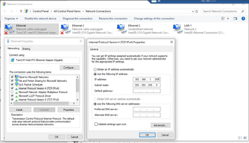
Next, we want to make sure to configure the ethernet port for the correct address and subnet to communicate with the Ethernet I/P device. Notice the network adapter now has the ‘TwinCAT-Intel PCI Ethernet Adapter’ description in the Network Connections menu.
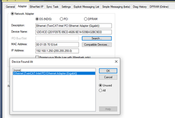
Now, back in the PLC Project, we need to setup the properties of the Ethernet I/P Scanner. In TwinCAT on your computer, setup the route target system as the address of the IPC. Double click on the device, ‘TC3 EIP Scanner’, to open its properties. On the adapter tab we can search for the network adapter that we just installed the runtime driver on. Select that adapter, and the MAC and IP Address you configured in the IPC should automatically populate in the fields on that tab.
Then, click over to the Settings tab and input an IP address and Network Mask. The IP address of the Master must be different than the static IP address on the IPC network adapter!

Now, you should be able to build the solution and start the PLC into run mode. At this point I was able to trigger the camera from the PLC. To do this I simply performed some online writes to the outputs mapped to the camera from the PLC program.
Learn more about DMC's Beckhoff expertise and contact us today to get started on your next project.