Recently, DMC Embedded has been looking for a platform that allows for rapid prototyping to show proof of concept. We wanted an off-the-shelf product that had room for modularity and easy expansion for various peripherals based on the needs of the prototype. We choose the M5 Stack ecosystem because the stacking nature of the product gives us the modularity were looking for while the wide range of expansion boards offer the freedom to add the features we need. This was the first product we tested, and its results were very positive.
The model we tested was the M5 Stack Core Basic. We chose this model for its simplicity, physical buttons, and validation that the most basic model can be used effectively. This model is equipped with an ESP32, SD Card slot, three physical buttons, a color LCD TFT screen, speaker, and GPIO pinouts. Additionally, we purchased a larger battery and a proto stack which all stacked together nice and clean. There is also a USB-C port used for charging and programming along with a power/reset button.
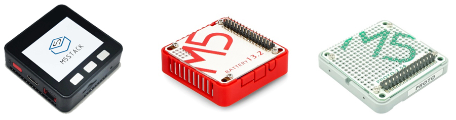
Left to right: M5 Stack Core Basic, Battery Stack, and Proto Stack
The device is based on two or three possible architectures, including Arduino, MicroPython, and UI Flow 2. MicroPython and UI Flow 2 can be combined since UI Flow 2 is a drag-and-drop language which is translated into MicroPython. The main gap between UI Flow 2 and base MicroPython is the online vs. offline aspects of the two. Since drag and drop most likely won’t be used, we’ll focus on the other two architectures.
UI Flow 2
UI Flow 2 is a web-based IDE that allows the user to flash and burn the device all through browser-based serial. It does this using the MicroPython environment which has a base firmware loaded to the ESP32, then replaces the main.py code for fast flashing and testing. I have supplied short tutorials for each of the methods at the end of the document or have provided the M5 curated document.
A nice feature in UI Flow 2 is the ability to design a UI in the IDE and have it created into MicroPython code. This helps when designing a screen since you can see how it looks in real time without having to flash the device each time a change is made. I did not use the drag and drop functionality much for main development, although I did use it to get instance reference to the source code. For example, to set up UART, I dragged an Init UART and Setup UART block to get the MicroPython code that showed how those functions are actually used. I did this for many peripherals to find out how to use them without referencing the source code directly.
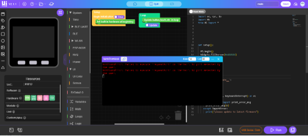
UI Flow 2 main IDE
I encountered one issue when using the UI Flow 2 cloud save function. My entire project seemed to have been deleted, and I couldn’t find out why. After that, I did my work in visual studio code and copied the code into UI Flow 2 for fast flashing and error checking.
Aside from that issue, I think a user could get very far with just UI Flow 2 and I would highly recommend it as a starting point to using the M5 stack as it demonstrates how the device can be used and can even write much of it for you using the drag and drop functions. Some functions that were tested and confirmed to work were UART, screen related changes, the buttons, write/read to the SD card, ISR, an async library, and programing the device.
Arduino
Since the device is based on an ESP32, Arduino is another option for using the device. This can be done through the desktop-based Arduino IDE. The M5 tutorial was generally fine although it did not show a step to get the specific device library files.
Once all was set up, I used example code to test the board and its peripherals. The same tests that I did on the UI Flow 2 setup were done in Arduino, all of which worked.
Another benefit of the Arduino framework is the C/C++ based language, as it is often used within DMC Embedded. Since this is a C/C++ based method, a major downfall was time. Being a compiled language, I lost a lot of time waiting for compilation and flashing of the device. Although I would prefer to use a C/C++ based language, I do not feel Arduino is the ideal environment to use the M5 in. It may have great applications depending on the use case if certain libraries are only found in Arduino. A benefit of Arduino over UI Flow 2 was that the error messages when compiling were much clearer.
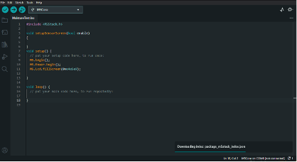
Arduino IDE with some sample code
MicroPython
Although I covered some of the functionality in the UI Flow 2 section, this section focuses more on a local setup of using MicroPython on the device. This method used a different base firmware from MicroPython directly. Because of this, I had to add libraries to the firmware for the MicroPython code to work.
When testing, I focused more on the accessibility of the device through command line interfaces. The goal was to use VS code extensions although at the time of writing none of them seemed to work anymore. Some good offline options are Thonny and PowerShell using esptool, ampy, mpremote, and REPL. The benefit of these is that you don’t need an internet connection to use them, and development can thus happen anywhere and without fear of the site being down or discontinued. This method was very quick and allowed for a similar workflow as seen in UI Flow 2. The only downside is setting things up to do this as it can be a bit confusing. I've included instructions below for the reader’s ease. Also, you can use scripts to make a simpler one-click solution. You can use the base UI Flow 2 firmware as a starting point as it has the needed drivers and libraries within it to use the M5 device effectively.
Tutorials
UI Flow 2
The tutorial provided by M5Stack is pretty good and is linked here. The general steps go as follows:
- Download M5Burner.exe
- Burn the related UIFlow2.0 firmware
- Choose COM port that the device is attached to and set baud to 1500000
- Open the UIFlow2 IDE here
- This requires you to make an account to save things
- Install drivers found here for your specific setup, I used CP210x_VCP_Windows
- Once in UI Flow 2, make a project and open it
- A simple demo of things working is to make the screen a color
- On the left side under the UI drop down select UI-> Screen and drag a “Set screen background color ‘Palette’” block to after the “Init built-in hardware at beginning” block
- Select a color
- In the bottom right corner press run
- A WebTerminal will come up and or a browser serial picker
- Choose a serial port that corresponds to your setup
- If this doesn’t come up press the chain link icon in the top left corner of the terminal
- Press the play button to send the code to the device, the screen should now be the color you picked
- To burn a file to the device to use on battery power
- Sometimes the burn button to the right of run works but if not follow the below directions
- In the WebTerminal select File, scroll down to main.py->Delete
- This will delete what is stored locally on the device
- Create a file called main.py in a text editor, paste your code there
- Press Send File to Here and select main.py-> Confirm
Arduino
The tutorial provided by M5Stack is pretty good and is linked here.
MicroPython
This documentation is not great nor is it clear. The tutorial I followed was here. A general guide is here:
- Either download a bin file from here or use the M5Burner.exe to burn on the UIFlow2.0 firmware. If you download a bin keep following, if not skip to step 7
- Open a cmd or powershell terminal
- Create a virtual environment for this project
- Run pip install esptool in the terminal, this will install the esptool
- Run esptool.py --port COMX erase_flash
- Change X with your com number
- If this doesn’t work, try esptool --port COMX erase_flash
- Run esptool.py --chip esp32 --port COMX write_flash -z 0x1000 YOUR_FW.bin
- This should be run where your file is located
- If this doesn’t work, try esptool.py --chip esp32 --port COMX --baud 460800 write_flash -z 0x1000 YOUR_FW.bin
- Your ESP32 will now have firmware on it
- At step 1.5 in the MicroPython tutorial it changes to this tutorial
- Now we will work on getting a main.py onto the device
- Run pip install adafruit-ampy
- Run ampy --port COMX put main.py
- Run ampy --port COMX run main.py
- You should now have your file running on the M5 Device
Useful Links
Learn more about DMC's Embedded Development and Embedded Programming services and contact us for your next project.