This article is the first of a series to help explain the basics of creating a base project using Epson RC+, Epson's software for development and simulation of an industrial robotic application. Epson offers a multitude of different industrial robots, covering a wide array of applications. The programming and configuration of the robots is done through their easy-to-use configuration software, Epson RC+, which offers many time-saving features and various add-on packages depending on the complexity of each application. We will cover the first steps of developing a robot application by making a new project, adding a robot, teaching a few points, and executing a simple program.
Create a New Project
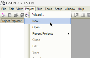
The first step is to create a new project. Create a new project by opening Epson RC+ and selecting Project -> New.
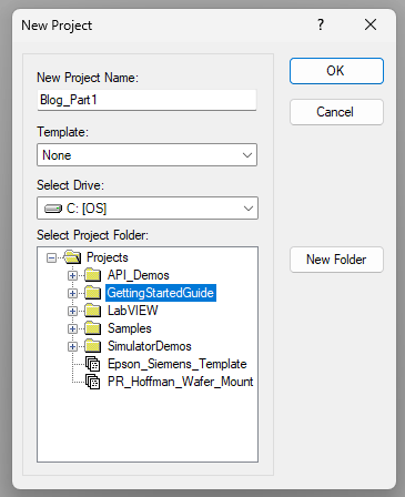
Give your project a name and select the folder you would like to save it in. You will notice that the Projects folder is at the location C:\EpsonRC70\projects on your computer. Once you have a name and folder selected, leave the Template as ‘None’ and then click ‘OK’.
Add a Robot
The next step is to configure the connection to the robot controller. There are three different ways to connect to a robot controller from Epson RC+. These options are USB, ethernet, or virtual. The USB option is with a direct connection to the robot controller’s USB-B port. The ethernet option is for a connection to the robot controller’s LAN port, where you can access the controller with its IP Address. The default is 192.168.0.1, but this can be changed later in the controller system configuration.
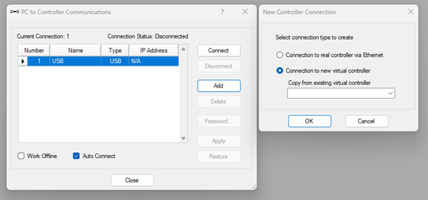
For this example, we will be using the virtual option, which connects to a virtual robot controller instance on your PC. On the toolbar select 'Setup -> PC to Controller Communications', and then click ‘Add’. Use the radio buttons to select the virtual controller and click ‘OK’. Before applying the changes, you can also rename the connection.
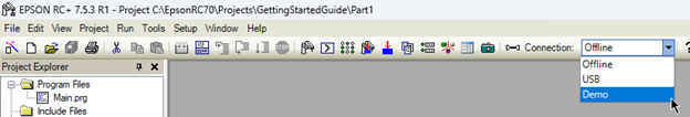
Next, we will attempt to connect to the newly added virtual controller by selecting it from the connection drop-down menu. The virtual controller will take a few seconds to initialize, but once it starts the words on the bottom right of the software will show you the controller is in Program mode and no robot is present.
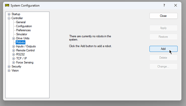
To add a robot to the controller, select Setup -> System Configuration. Under Controller -> Robots, you can add a robot. If this is a virtual controller, you may need to add a dummy serial number before it will accept the input. The robot controller will reboot after you add a robot. Close the System Configuration.
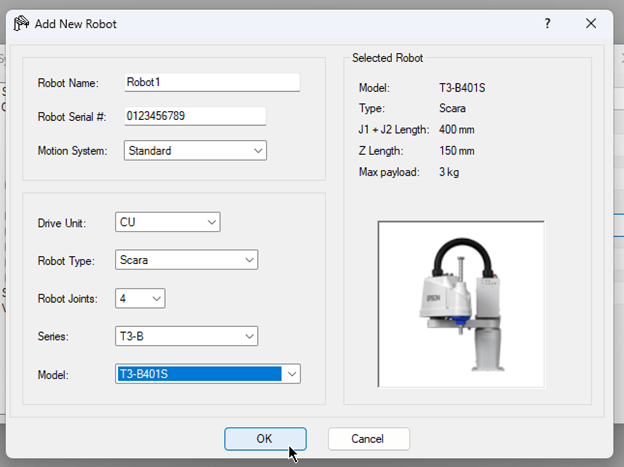
Add your robot model to the project.
Teach the Robot
Open simulator from Tools -> Simulator or clicking  on the toolbar. The simulator window will show the robot live while it is moving around. In a later blog, we will go over the simulation environment in more detail.
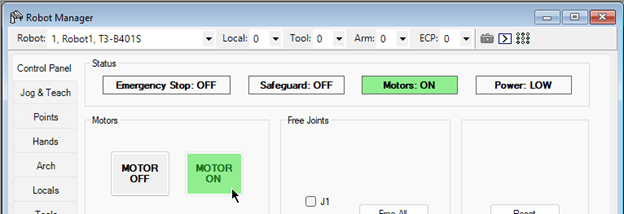
Next, open Robot Manager from Tools -> Robot Manager or clicking  on the toolbar. The Robot manager is the equivalent of using a teach pendant that you can control from your computer when connected to the robot. In this window you have access to a lot of different functions including motor and power control, jogging, teaching points, configuring motion limits, and much more. In the Control Panel tab, click the ‘Motor On’ button.
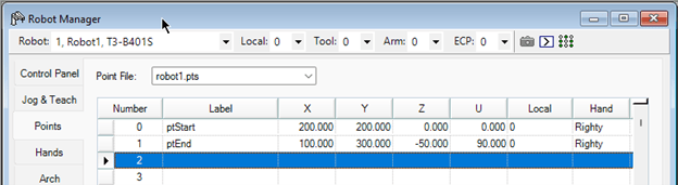
Next, navigate to the points tab, add two points as shown in the screen shot below.
Now, navigate to the Jog & Teach tab. Under the execute motion tab, select ‘ptStart’ from the Point: drop-down and click ‘Execute’. You will be able to see the robot moving from where it starts to the configured point ptStart. A small pop-up window will display while the robot is in motion where you can stop the command if needed. Now, select the second point ‘ptEnd’ and execute the motion again. The robot will now move from ptStart to ptEnd. Our next step will be to write a simple program that can automatically move between these two points.
Execute a Simple Program
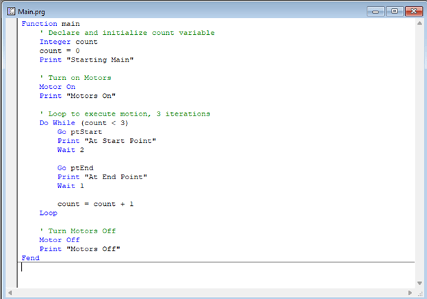
Our next step will be to use these two points defined and have the robot automatically move between them. Using the screenshot below as reference, add a couple commands to the main program with two points. The logic below defines an integer used to count the number of cycles, turns the servo motors on, and loops over the commands to go between the two points we defined above with a short pause in between. The Go command is a type of joint move to initiate motion, the Print command will write the values to the output window (a useful debugging tool), and the Wait command will initiate a program pause for the defined time in seconds. The final command is to turn the motors off and the function is complete.
Send the updated code in your program to the robot controller with selecting Project -> Build. This will compile the project and load it to the controller automatically.
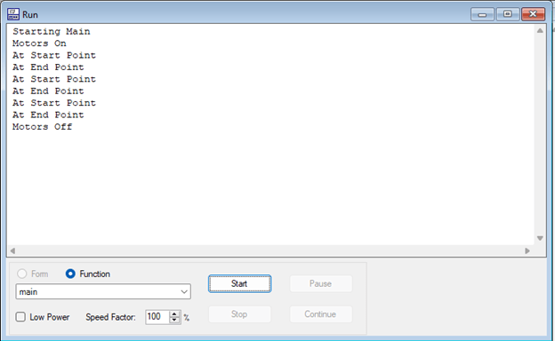
Finally, we can start the program from the Run Window, found under Run -> Run Window or clicking the icon  on the tool bar. Here you can select any function from your program to test, using the drop-down menu under the Function radio button. Since we only developed logic in the main program, we will use the main function as our selection. The output of the program should reflect the screenshot below.
This example is just the beginning of what you can achieve with an Epson industrial robot. In the subsequent articles of this blog series, we will be introducing and demonstrating more in-depth aspects of programming, simulating, and commissioning with Epson industrial robots.
To learn more about DMC's experience and knowledge of Epson Robots visit our Manufacturing Automation & Intelligence page and contact us today for your next project.