Setting up static navigation buttons that bring operators to a single screen when pressed can be sufficient for simple systems; however, it can be difficult to adequately display all necessary screen elements for larger or more complex systems.
With dynamic navigation, the available screen space can be used most efficiently to allow users of the system to move between all system information quickly, as well as allow for easier configuration.
In this example, we will use Rockwell Automation’s Logix Designer Programmable Logic Controller (PLC) programming software (version 35), Rockwell's FactoryTalk View SE Human Machine Interface (HMI), and Supervisory Control and Data Acquisition (SCADA) programming software (version 13).
Static vs. Dynamic Navigation Buttons
Dynamic navigation buttons share many of the properties of static navigation buttons. These properties are:
- Button text indicating the screen that will be opened upon pressing the button
- The name of the display to open when the button is pressed
- An indicator to indicate that the screen associated with the button is currently being displayed
The main difference is that dynamic buttons allow this information to be changed via PLC logic or operator inputs. This logic will depend on graphical and operational decisions that will vary between projects due to specific client needs. Our buttons must be able to provide a simple interface that can work seamlessly with client requirements.
PLC Data Structure
We will begin by setting up a User-Defined Type (UDT) on our PLC that will provide all button information to our HMI. The UDT will contain the following elements:
- sButtonText
- sDisplayName
- bVisible (for button visibility and ability to be clicked)
- bIndicatorVisible
sButtonText will indicate which screen will open when pressed. sDisplayName will match the name of the display as it is called in the FactoryTalk View SE HMI project. bVisible will control when the navigation button is visible on the HMI, and, thus, when it can be pressed; this can also be substituted for a bEnable tag that only enables the button if we want it to always remain visible. bIndicatorVisible will indicate that the current screen is associated with an individual button.
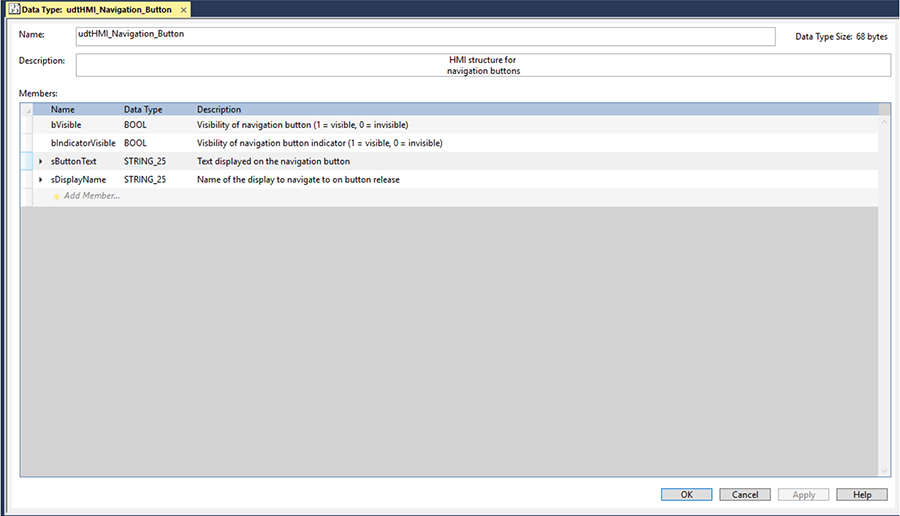
Depending on client needs, we could also add more elements to this UDT. For example, if we needed to indicate the presence of an alarm related to an element on a button’s screen, we could add a bAlarmActive BOOL.
PLC Logic
The next step is to set up PLC logic to write this information in the button’s HMI UDT. In this example, we will put all this PLC logic into an AOI so that we can simply instantiate an instance for each navigation button that we wish to set up.
Our AOI will have the following inputs, as well as an InOut for our UDT. In this case, it is called HMI because this is the information shared with the HMI.

The PLC logic contained in this AOI will be simple, as we are taking inputs from the AOI and moving them to the HMI structure or evaluating elements in the HMI structure.
Rungs 0 and 1 move the button text and display name inputs from the AOI to the corresponding elements in the HMI structure.
Rung 2 checks if the button text is blank to determine whether the button should be displayed and clickable on the HMI. This is because, in this example, we are assuming that the button text AOI input will only be set when the button should be displayed; although, this can vary depending on how the system of providing buttons their info is set up.
Rung 3 verifies whether the name of the screen being displayed on the HMI matches the name of the screen associated with the button and, if so, displays an indicator on the navigation button.
External Logic to Set Button Information
Logic external to the button instances must be put in place to properly write to the button inputs. This system will rely on factors like how the client specifically needs the navigation to function, memory constraints of the PLC being used, and configuration needs.
An example system that could be implemented is creating an array of button text and an array of display names with an INT tag for the index of the arrays that should currently be used. This index could be set by pressing static navigation buttons on the HMI. The static buttons could correspond to a group of devices and the dynamic navigation buttons could then be used to open the screens of the specific devices when pressed.
But there are many ways other than the given example to set up the system to provide information to the dynamic buttons.
HMI
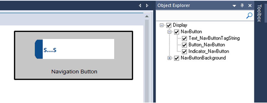
We will now set up the button on the HMI: because we would like these buttons to be reusable, we will mark the buttons as a global object in FactoryTalk View SE.
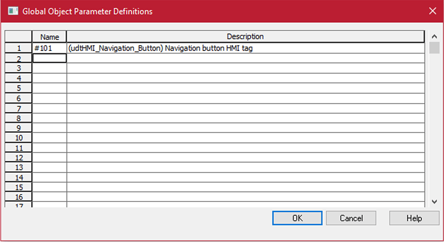
The only global object parameter that will need to be passed in is the path to the button’s HMI structure.
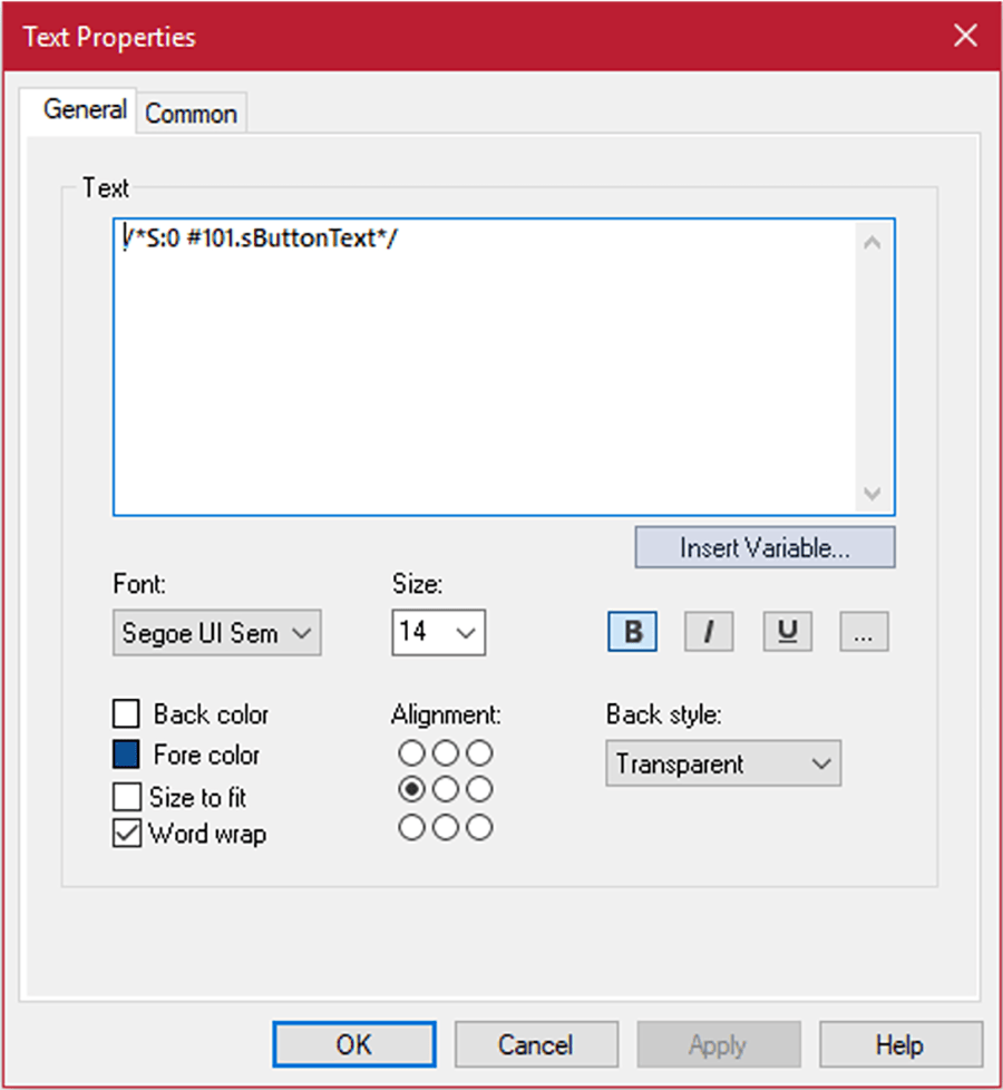
The button text object will display the value of #101.sButtonText.
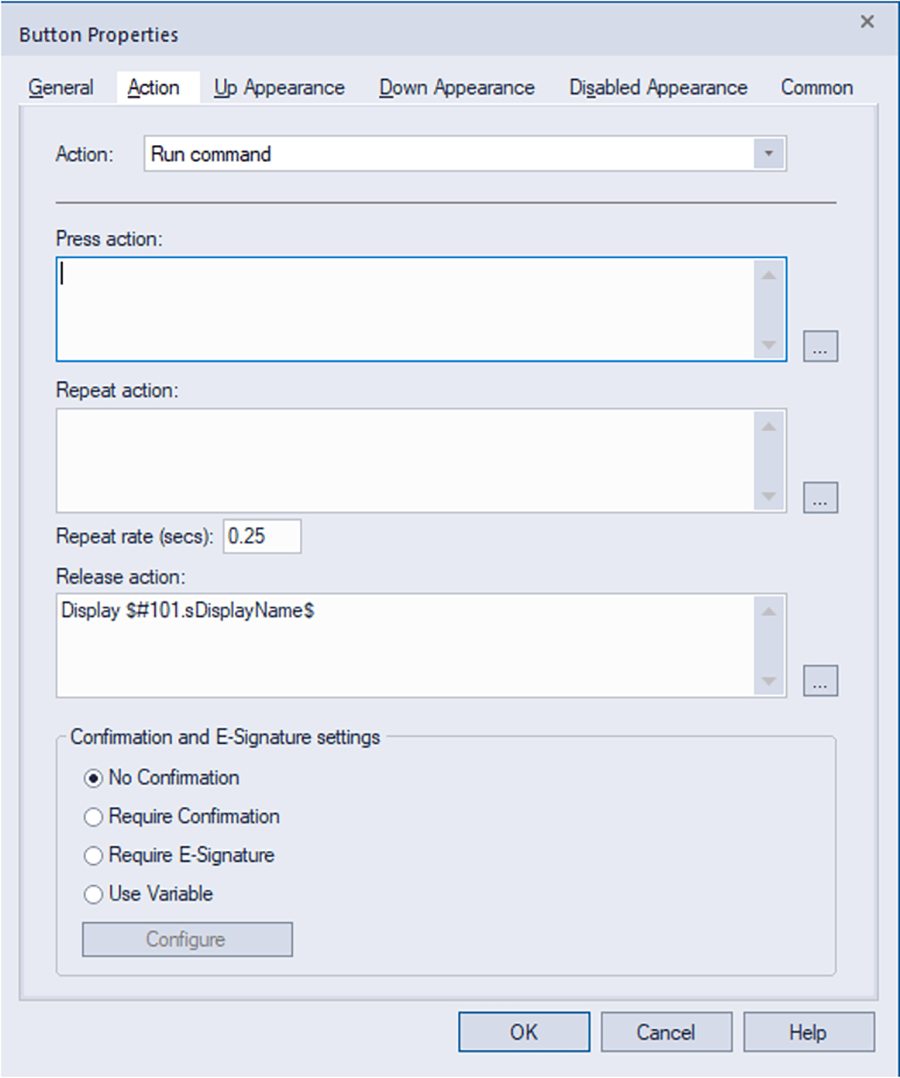
The button’s action will be to open the display with the name of our #101.sDisplayName tag.
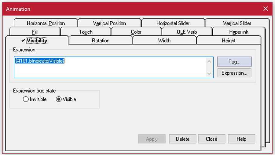
The indicator will have a visibility animation linked to the #101.bIndicatorVisible tag.
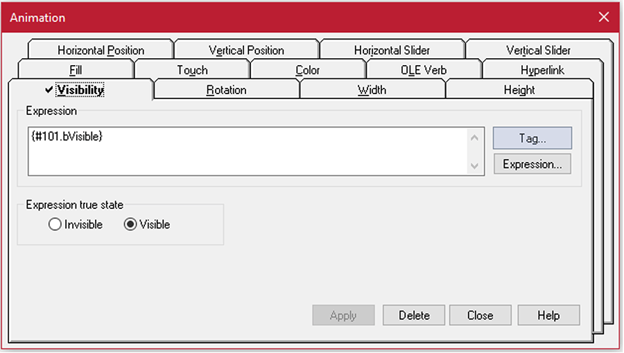
And the button object itself will have a visibility animation linked to the #101.bVisible tag.
Saving on Memory Usage
Dynamic navigation requires the use of a large number of strings, so it may be necessary, depending on PLC memory capacity, to move this information to the HMI project. FactoryTalk View SE makes this easy with macros. The button text, display name, and any other information that the navigation button needs can be put in a macro and applied to the button.
For this example, we will create two macros. The first will be called SetDynamicButtonValues and will take in the inputs for the tag path, the navigation button’s HMI tag, the button text, and the name of the display to open on button press.

The next macro will use SetDynamicButtonValues to populate the dynamic navigation buttons. In this example macro, we are assuming that our system has several groups of different devices that each has their own screen, and we have five dynamic buttons on our HMI.
These devices are a drill, lift, hydraulic pump, set of sensors, and a leak tester. The names of their corresponding screens in the HMI project are DrillControl, VehicleLiftControl, PumpControl, SensorMonitoring, and LeakTestMonitoring, respectively.
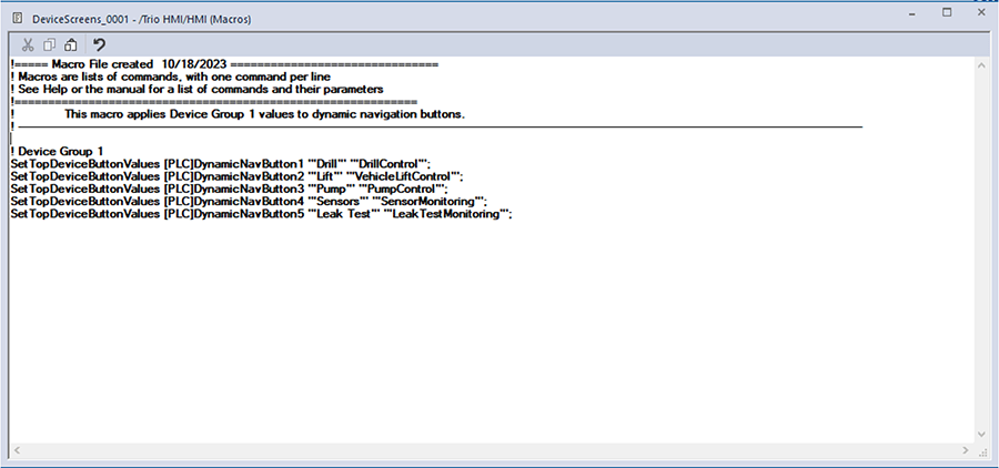
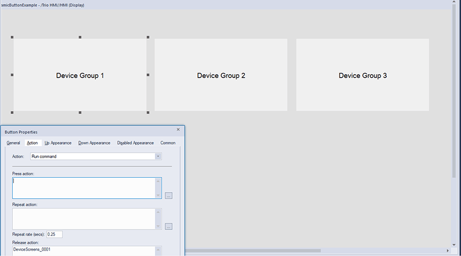
We could then duplicate this macro for our other device groups and change the name to DeviceScreens_0002, DeviceScreens_0003, etc. Then, we could add a call to each of these macros to the action of static buttons corresponding to each button group.
Using Dynamic Macro Calls
A useful feature of macros in FactoryTalk View SE is that you can make macro calls dynamic. If we wanted to use that feature in our previous example, we could suppose that our system has multiple assembly lines where groups of devices are often switched out.
In this hypothetical case, our PLC has an INT tag called Line1.HMI.iGroup1DeviceScreens. An operator can change the value of this tag based on which device group they are using.
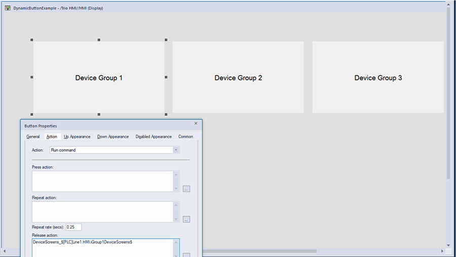
To allow this function, we can simply change the linking on our device group buttons to concatenate the beginning part of our macro name (“DeviceScreens_”) with an identifier number that corresponds with the desired device group. We would also need to make sure that DeviceScreens_#### macro is set up in the HMI program with the appropriate button text and display names.
With this set up, when the operator changes the device group number on the HMI, clicking the Device Group 1 button will open apply the appropriate values to our dynamic navigation buttons.
Depending on specific project needs, setting up dynamic navigation can be a convenient way to display a large amount of information in an efficient manner. FactoryTalk View SE can be used in interesting ways to save on PLC memory usage as well as make your project much more configurable.
DMC is a Rockwell Gold System Integrator. Learn more about our FactoryTalk services and contact us for your next project.