Beckhoff is one of the premier automation vendors in terms of motion control. By basing its fieldbus on EtherCAT, Beckhoff can achieve deterministic performance with flexible topologies, both of which are necessary for complex motion projects.
DMC has a lot of experience with Beckhoff motion projects and has developed libraries to reduce development time. Please reach out to DMC if interested!
In this blog we will add an axis, move the axis virtually using a couple of different methods, and get into the configuration and diagnostics in TwinCAT. General TwinCAT knowledge is assumed for this blog.
TwinCAT NC Interface
To explore the TwinCAT NC Interface, an axis will have to be added to a project. Open a new project and RMB (Right Mouse Button) MOTION >"Add New Item...">"OK."

Next, add an axis by RMB Axes >"Add New Item..." Name the axis and press "OK."

At this point, activate the configuration so that axis is on the target.
Click on the axis that was just created. This will open a window with several tabs.
Settings
The Settings tab is where the axis is connected to physical hardware along with the PLC.

When a drive is added to the project, it will show up when clicking "Link To I/O." When connected to a device, the axis will send commands and receive status from physical hardware. When connected to nothing, the axis is simulated.
To control an axis from PLC code, the axis will need to be connected via "Link To PLC." This will happen in the next section. For now, the axis can only be controlled via the Online tab.
Online
The Online tab allows for basic control of an axis. Even when connected to the PLC, the Online tab can be used if there are no PLC commands overwriting it.
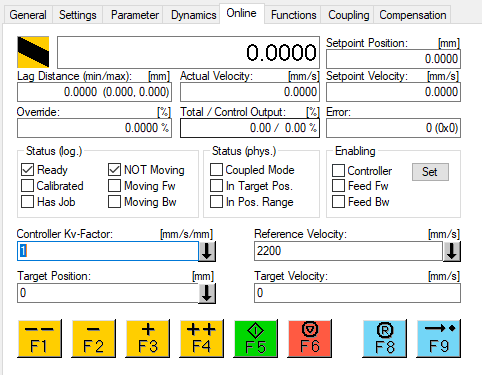
Since this axis is not connected to the PLC, it needs to be turned on before moving. Press the "Set" button and press "All." This will turn on the axis at 100% override.
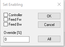
In a situation where the axis should never be moved backward or needs to be run at a reduced velocity, you can choose these options in the above popup.
Once "All" is selected, the 3 boxes in the "Enabling" boxes should be checked. We can now jog the axis by pressing the jog buttons at the bottom of the screen. The position of the axis will change accordingly.
Functions
After you've had enough fun jogging the axis, head over to the Functions tab.
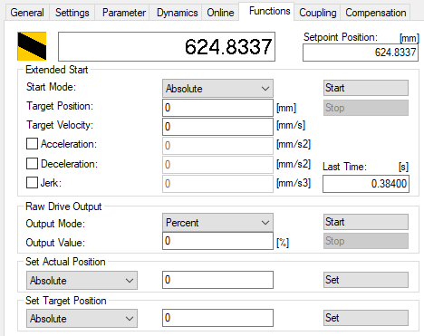
This is where more precise motion commands can be issued. For example, setting a "Target Position" and "Target Velocity" and pressing "Start" when "Absolute" is selected will send the axis to the position. There are several other movements in the dropdown that are worth trying out.
Another powerful feature of this tab is the ability to set the position of the axis without actually moving it. Type a number into the "Set Actual Position" filed and press "Set" and the position of the axis will change to that position without moving.
Parameter
Now that we have the basics of axis movement down, let's make some parameter changes for how the axis behaves. In the Parameter section, a lot of the properties are set based on the drive and motor combination that are brought into the project (this will be discussed later); however, there are other properties that are very application specific.
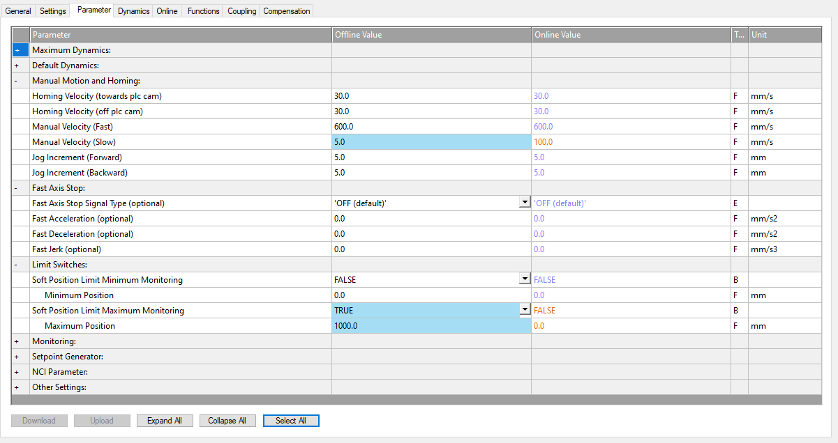
Here, the "Manual Velocity (Slow)" has been changed to 5.0 mm/s. This will affect the axis when pressing the "+" and "-" in the Online tab. The red text in the "Online Value" indicates the values are different on the target than in the project. We will need to activate configuration for these changes to be made. The second parameter that has been changed is enabling "Soft Position Limit Maximum Monitoring" and setting the "Maximum Position" to a value of 1000 mm. This will prevent the axis from going to a position greater than 1000 mm. Activate the project and see what effect these have!
Axis_REF
Next, let's connect the axis to a structure in the project so that we can control the axis through code!
The datatype TwinCAT used to do this is AXIS_REF, which acts as an interface between the PLC and NC. At the most basic level, this datatype is passed into MC function blocks as an IN_OUT variable to control the axis. In many instances, these MC blocks are wrapped up in another function block to make it easier to control, but, ultimately, these blocks are used to control the motion on an axis.
To add an axis to the project, we will need the Tc2_MC2 library. Add this by going to References->Add Library->Tc2_MC2. Add an axis (of type AXIS_REF) to the project in a new FB_Axis (Structured Text) function block. Be sure to call this FB from MAIN!
Build the project, and make the linkage in the NC interface to the PLC.
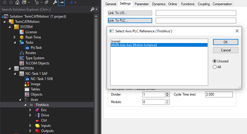
So what is this actually doing? Taking a look at the definition of AXIS_REF, you will see that it exposes a physical input and output to and from the NC interface. This allows for the PLC and NC interface to exchange information. The PLC is sending a Control word (and other commands) and the NC interface is sending back a State word (and other status information). You will also notice that Inputs and Outputs in the side bar have been automatically linked when adding the axis.
Connecting to Code
To gain a solid understanding of what is happening under the hood, let's add a couple MC functions blocks to control an axis. Add a MC_Power and MC_MoveAbsolute to FB_Axis. Since we will control it from the variable table, only the Axis needs to be connected to the MC blocks.
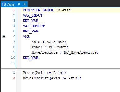
Download this to the PLC and login. When opening up the Power function block, you should see something very familiar!

These are the exact properties that are seen when going through the Online tab in the NC Interface, so, writing all three of these properties to TRUE will turn on the axis. This can be confirmed by going back to the NC Interface and verifying the 3 boxes in the "Enabling" boxes are checked.
Now that the axis is on, move it to a position of 100 by writing it into the "Position" input of the MC_Absolute block. Make sure to specify a "Velocity" as well. Set "Execute" to true, and the axis will begin to move.
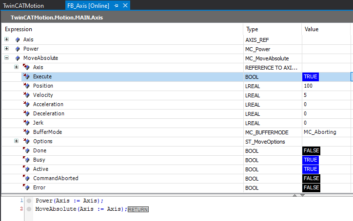
This can be verified by the "Active" bit being true while the axis is moving and the "Done" bit being true once the axis gets to the position. The NC Interface will also show the live position as it is moving. Again, this should look very familiar as it has the same inputs as the Function tab in the NC interface.
Utilizing a General Motion Function Block
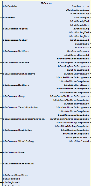
This is where DMC's experience can be of value. DMC has developed a general motion function block, so it is not necessary to add all the MC function blocks. Rather, this acts as a wrapper. For example, instead of adding MC_Jog, all that needs to be done is turning on the `bInCommandJogFwd` bit. The logic inside of the function block handles the scenario when multiple commands are called at the same time, aggregates all the errors, and outputs when a specific command has been completed.
Connecting to Hardware
The final piece is to actually connect the NC interface to hardware.
To do this, some hardware must be added.

Once the drive is added, another axis in the NC Interface will also be added. Since we already have an axis configured, delete the one that was just created. Go ahead and link the NC axis to the drive we just added.

Now, we have a fully functioning NC interface that is ready to be connected to real hardware! Unfortunately, there isn't much more we can do after this since we don't actually have this hardware but it's worth the exercise.
Beckhoff Hardware
Using Beckhoff drives and motors with TwinCAT obviously comes with its advantages. First off, both will be readily available to add as hardware. The drive will be available in the hardware tree, and the motor will be available in the Drive Manager. We will get into Drive Manager and Drive Manager 2 later, but this is where a motor can be specified. This will populate a lot of properties that need to be set in both the NC interface and drive's Startup parameters (to also be discussed later as well)
3rd Party Devices
For third party devices, configuration files will need to be obtained from the manufacturers website or Beckhoff support. For example, a simple "Yaskawa Drive Beckhoff" yields some great guides with instructions to install files. If that does not yield positive results, Beckhoff support can make these configuration files based on the drive or motor specifications.
To be able to add a 3rd party drive, the configuration file (.xml) will need to be placed in the `C:\TwinCAT\3.1\Config\Io\EtherCAT` folder. For a TwinCAT project to recognize the new file, the devices must be refreshed by going to `TwinCAT -> EtherCAT Devices -> Reload Device Descriptions`
Drive Settings
Just like the NC interface, there are several tabs of settings associated with the physical hardware. Some of these parameters are shared between each other while some are hardware specific.
General, EtherCAT, Online
These tabs speak for themselves and usually do not need to be configured. These tabs exist for any piece of hardware added, regardless of if it is a drive.
DC (Distributed Clock)
This is another tab that should not be touched unless there is a complete understanding of what needs to be set and why.
Process Data
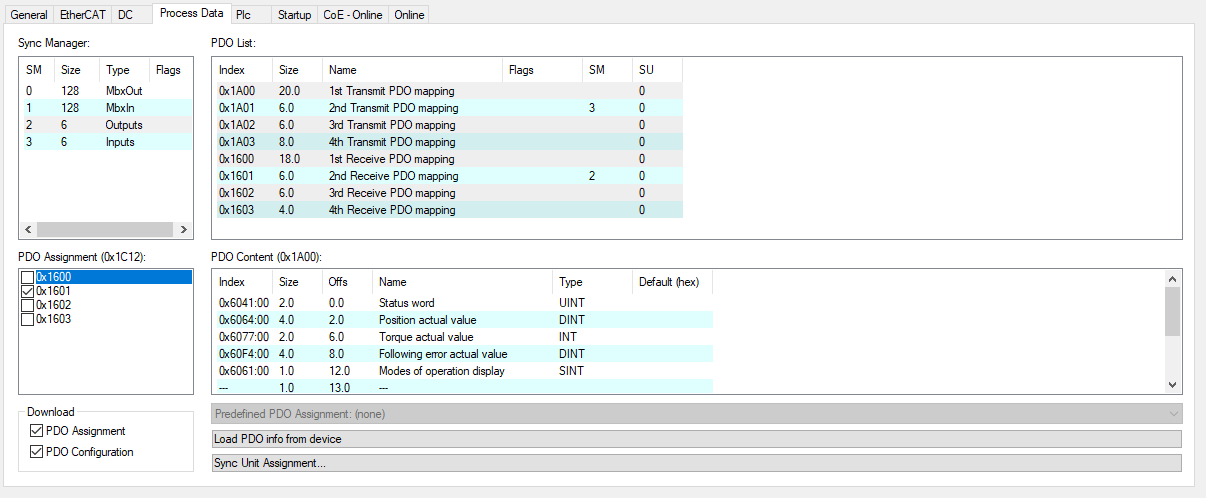
In this section, the PDO's (Process Data Object) of the drive can be edited. PDO's are parameters that are cyclically passed to and from the PLC. The parameters can then be linked to variables and used in code.

So, let's say we need to monitor the torque of the drive to know when to move to the next state in a sequence. This can be done by simply adding the PDO and then linking it to a variable in the PLC. RMB in the "PDO Content" window and press "Add New Item..."
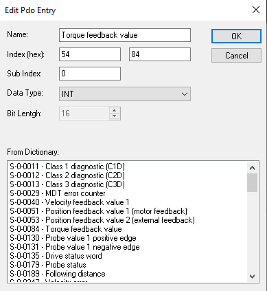
Find the "Torque feedback value" and press "OK." It will then show up in the hardware tree.
Some drives will have multiple sets of mapping available. Depending on what is useful for the application, choose which one(s) are necessary by toggling the check marks in the "PDO Assignment" area.
For Beckhoff drives, the Dictionary will contain all of the available PDO mappable content. For third party devices, these may not be readily available and may require some digging into the documentation. For example, here is an excerpt from a Yaskawa EtherCAT communication guide.
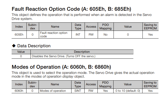
For the first parameters, this would not be able to be added because of the No under PDO Mapping; however, to add the second parameter, adding the index, subindex, and data type in the window above will add this parameter.
SoE - Online
Going slightly out of order, this is where the parameters of the drive can be viewed and also modified.
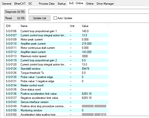
A parameter can be changed by double-clicking on the value.
Startup
The Startup tab contains the parameters that are written to the drive on startup.
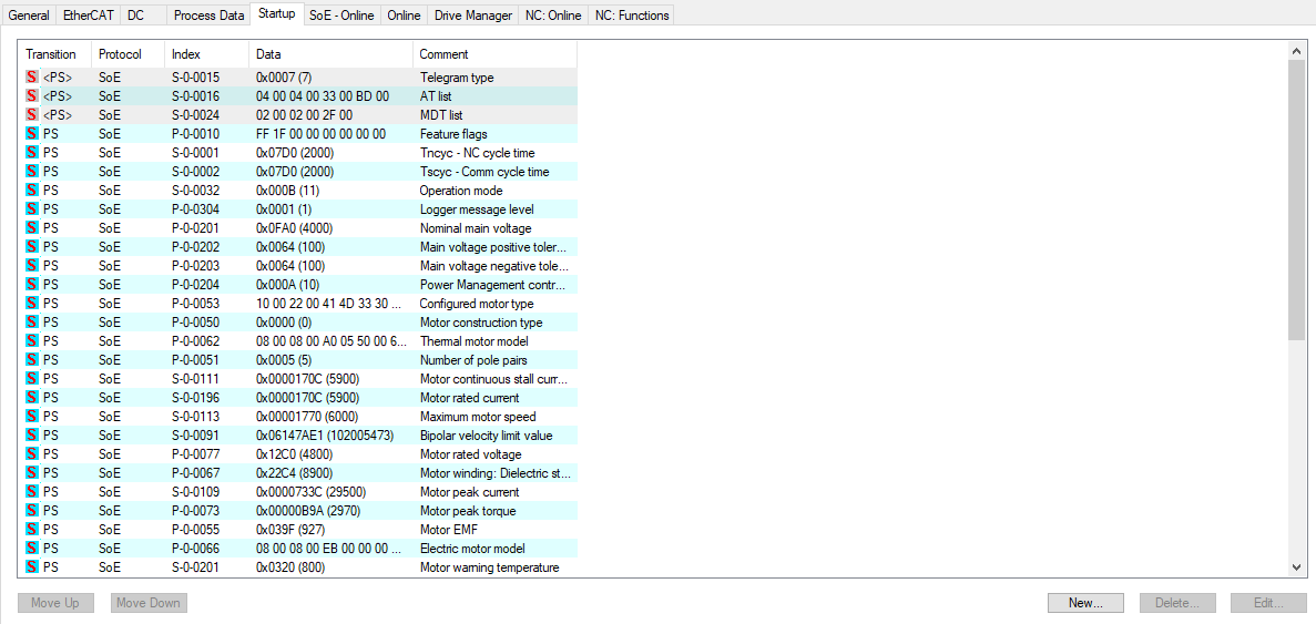
So, if a parameter is changed in the SoE - Online tab and the parameter also exists in the Startup tab, then the change will get overwritten on the next power cycle if it is also not configured here; therefore, it is very important to change the value in the Startup tab as well once the parameter change has been validated.
Another scenario is where the parameter is changed in the SoE - Online tab but the parameter does not yet exist on the Startup tab. In this case, the parameter will be retained at the value through a power cycle; however, it is still very important to then add this parameter to the Startup tab in the event the drive fails and a new one needs to be added. Without adding that parameter to the Startup tab, there is no record of this parameter ever being altered.
For Beckhoff drives, Drive Manager (2) is the most useful tool for what is going wrong. This is a place where all drive information is laid out in a useful way and error messages can easily be read.
Drive Manager
This is the original version, which is available when clicking on the drive in the hardware tree.
After adding a drive, the first thing that should be done is add the motor and feedback type. As mentioned before, this will set a lot of very important parameters on the drive and NC interface.
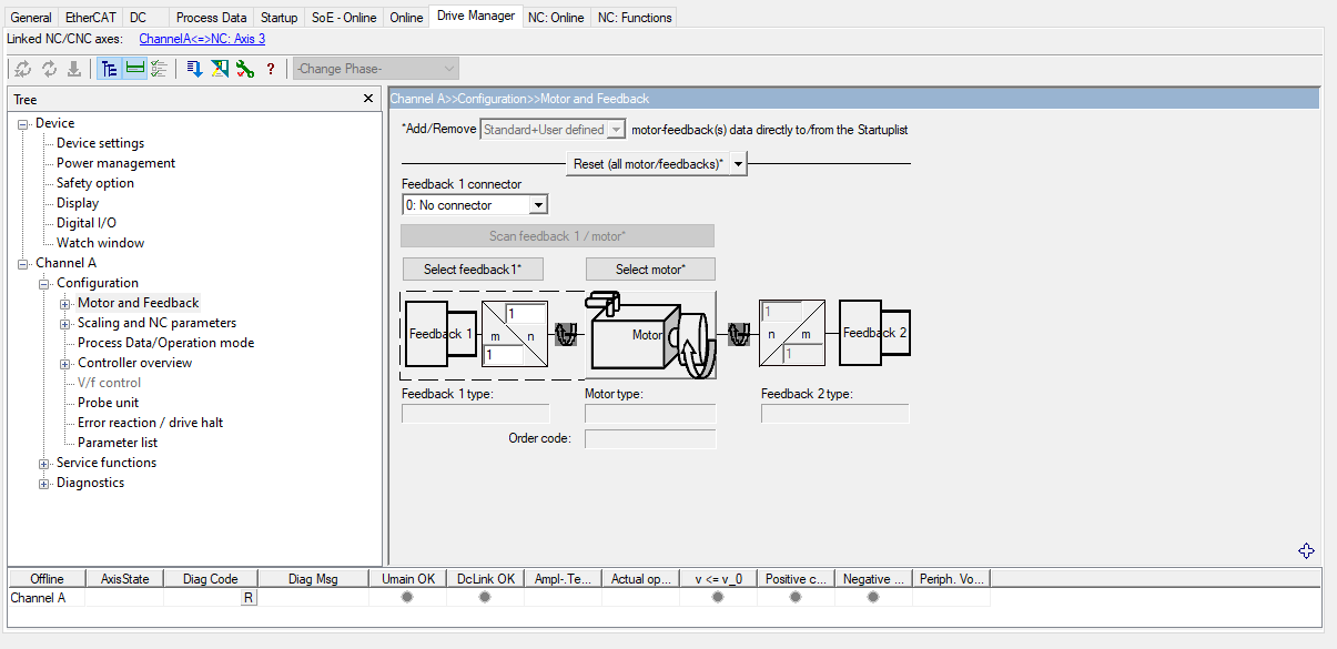
This is another very important parameter that needs to be set in the distance per motor rotation when taking into account gearbox and ratio. This can be done below.

Drive Manager also gives you the ability to change parameters of the hardware. Additionally, this window gives the user the ability to add/update the parameter to the Startup tab: which is very important, as discussed previously.
Pressing the greyed-out button with the down arrow will make parameters active on the drive from this window. Pressing the button with the blue down arrow will allow you to add any parameters to the Startup tab that differ from the current/default value.
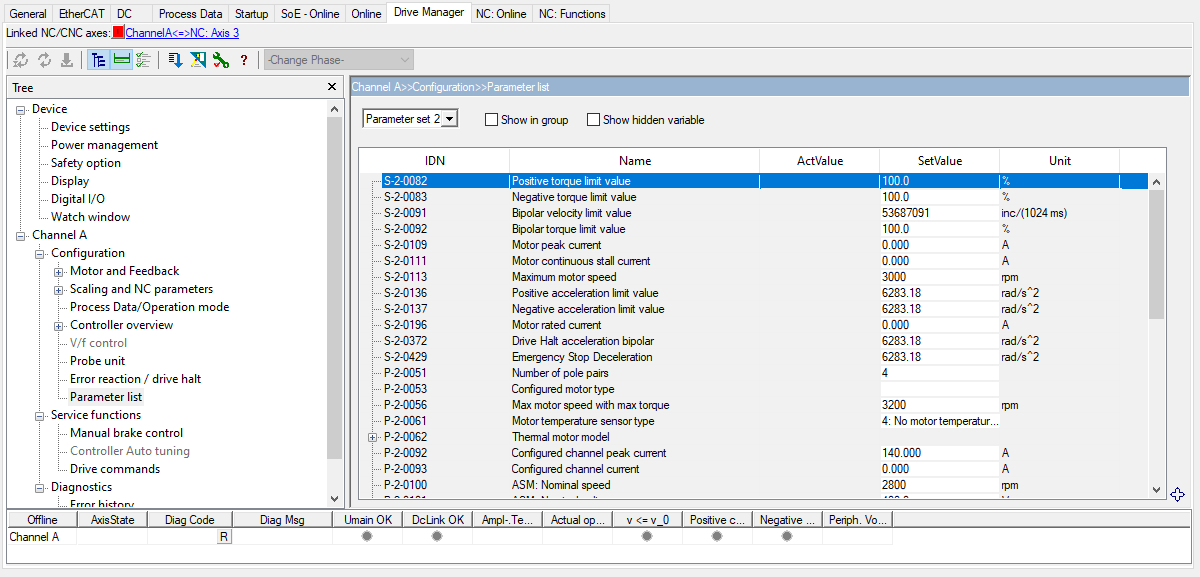
There are several other windows, but the most important remaining one is the "Error history" window: which is located under the Diagnostics section. Here, a list of errors can be seen, and this obviously can be crucial when trying to troubleshoot a machine.
Drive Manager 2
Drive Manager 2 is the new and improved way to commission and diagnose Beckhoff drives. To use Drive Manager 2, it will need to be downloaded from the Beckhoff website.
Once installed in the project solution, add a TwinCAT Drive Manager 2 Project. It will then detect all available drives.
The benefits to Drive Manager 2 is a better look and feel that is easier to navigate. All of the information from the original Drive Manaager exists in 2, but it just might be in a different location.
For the drive as a whole, the parameters will be located here:
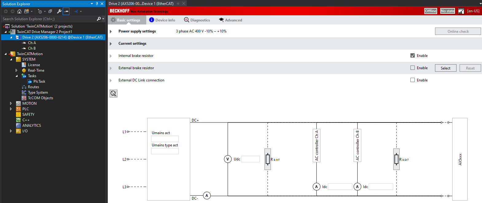
Then, for axis specific parameters, clicking on the individual channel will show screens similar to the Motor and feedback section in the original Drive Manager.

Although this was mentioned in the previous section, this is worth repeating. When troubleshooting a drive, this is the first spot you should go. A history of all drive errors is very powerful when troubleshooting a system and can often tell a story of what actually happened.

Conclusion
This is just scratching the surface of Beckhoff motion. Gearing, camming, coordinated motion, and CNC are just a few others that Beckhoff excels at. Be on the lookout for some advanced motion control guides in the future!
Learn more about our partnership with Beckhoff and our Motion Control Engineering and Servo Systems expertise, and contact us today for your next project!