Many MagneMotion systems use a PLC to coordinate the movement of vehicles within a greater system. While a Node Controller controls the actual motors of the system, a PLC is used to tell the Node Controller where on the track each vehicle should go. In part three of this blog series, we will go over how to set up your MagneMotion Node Controller to be controlled by a Rockwell PLC.
MagneMotion Guide Series
Step 1: Setting up the Node Controller
The first step is to make sure that the Node Controller is configured to be controlled by a PLC.
In the MagneMotion Configurator Tool, select PLC EtherNet/IP in the Configurator Tree and check the box for Use a PLC for Host Control. Now, a series of additional PLC options should be available. For most of these, it will be fine to leave them as defaults but you will need to set the IP address for your PLC and enter the PLC slot that the Node Controller will be communicating to.
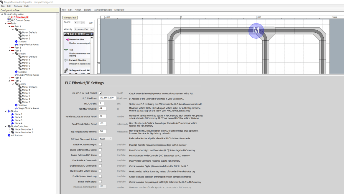
You will want to ensure that the PLC Max Vehicle ID is large enough to handle all the vehicles that might possibly be in your system. It might also be worth turning PLC Host Disconnect Action from “None” to “Suspend.”
Step 2: Using the Application Code Manager
To create the PLC program for your system, open Application Code Manager and go to File -> New Project. Select the type of project you want to create and click Next.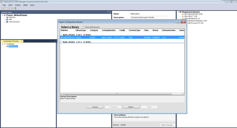
Enter the name of your project and hit Finish.
If you do not already have the ICT library registered, right-click on Registered Libraries, select register, and then select the .HSL4 file you want to register. You can find the ICT library files here.

On the left-hand panel, right-click controllers and click Add New. In the popup, select the type of PLC controller you are using and enter a name for the PLC. Hit Finish when completed.
In the new controller right-click Tasks and select Add New Task. This brings up a prompt to create a new controller task. Create it as a continuous task and name it appropriately.
Now, right-click the task you just created and select Add New. In the popup that appears find raM_Dvc_DH_MM and click Next.
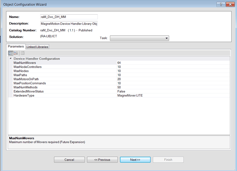
In the menu, you can now configure parameters for your PLC code; such as the maximum number of movers, max paths, and nodes etc. You can set these values now, but they can also be easily changed in the PLC code. However, one value that is more difficult to change once the PLC gets generated is the MaxNumMethods value. This value is the maximum number of ICT library AOIs in your project. If you have a particularly large system, you might want to increase this to 100 or 150 to afford yourself some flexibility and scalability.
Next, go to the Linked Libraries tab and hit Auto Create. This will generate all the AOIs and udts that are needed to run the default MagneMotion routine.
For the main task of the PLC, select your task again, right-click, and select Add New again. In the pop-up menu, select raM_Tec_MM_Station and add that to the project.

There are various other ICT Library AOIs used for controlling MagneMotion systems, but with these two additions we should be ready to start. If you know of any additional ICT AOIs you would like to use for your project, feel free to add them now.
Finally, in the Controller Preview tab right-click Controllers and select Generate Controller to export your configured PLC as either an ACD file or as an L5X file.
For additional reference, there is a quick start guide included in the ICT library download.
Step 3: MMI Tags
Assuming the Node Controllers for your system are set up properly (see MagneMotion Guide Part 2: Starting up and Commissioning a Track if not), then the Node Controller should already be trying to reach a PLC at the IP address you entered in the configuration file.
In either NC Host or the log file from the Node Controller webpage, you can verify if the PLC is properly connected to the Node Controller. If the EtherNet/IP indicator in NC Host is labeled Up, then you are all set.
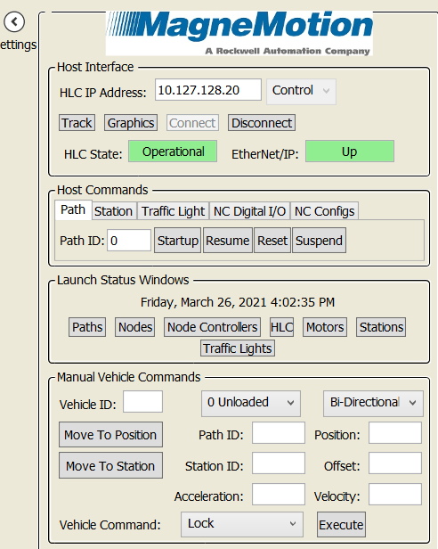
However, if the EtherNet/IP link is Down you will need to troubleshoot the connection between the Node Controller and the PLC. Verify that the IP addresses of the Node Controller and the PLC are correct, there is a valid network path between them, and the subnet mask for each device is properly set.
Once the communication from the Node Controller to the PLC is set in NC Host, you should either see that the EtherNet/IP link is Up or you will see that the link is flashing between Up and Down.
If the link status indicator is flashing, that means the Node Controller can reach the PLC but there is some conflict between the PLC code and the Node Controller configuration file.
In the PLC, there should be a list of controller-scoped tags with the MMI prefix. The Node Controller reads and writes to these tags in order for the PLC to control it.

To fix the Node Controller and PLC communication, you will need to make sure that all these arrays are large enough to handle the information required by the Node Controller. You can find out which tags are the issue by viewing the High-Level Controller Log from its webpage.
Each tag must be the size of all the elements it needs to control plus one. For example, if you have ten paths, the tag MMI_Path_Status needs to be size 11. This is because the Node Controller begins indexing at 1 so path three’s status information is found in MMI_Path_Status[3].
Go through each MMI tag and make sure it is the right size. For the tag MMI_path_ml_faults_status, the size needs to be the number of paths by the largest number of motors in a single path. So, if you have ten paths and the largest path had six motors this tag would have to be size [10 + 1, 6 +1] or [11,7].
The Vehicle Status tags will need to be sized based on the maximum number of vehicles defined in the Node Controller’s configuration file.
 There are also some tags scoped to the raM_Dvc_DH_MM program that were created by ACM. In order for the device handler for MagneMotion communication to work, these tags need to be the same size as their corresponding MMI tags (i.e., the Path tag needs to be the same size as the MMI_Path_Status tag).

With all these tags properly sized, you should now see a consistent green UP message in NC Host for EtherNet/IP communication. If you still do not see a consistent Up displayed, view the High-Level Controller’s Log File for additional information on which tag to check.
Step 4: Configuring the MagneMotion Connection
Now that the Node Controller to PLC communication is set up, there is just one step left to get the PLC properly communicating to the Node Controller. This is done using the ICT library’s configuration AOI.
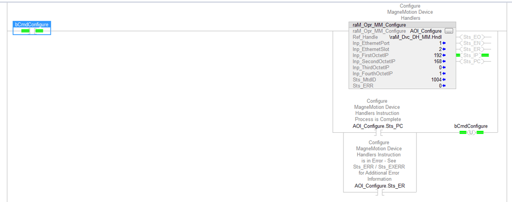
The job of this AOI is to configure the communication between the PLC and the Node Controller so that the PLC will know where to send commands. Here are the inputs to the AOI and how to properly set them:
- Ref Handle: This must be the Hndl tag in the raM_Dvc_DH_MM program to connect the AOI to the device handler. This tag should already be public so you should be able to just input \ram_Dvc_DH_MM.Hndl
- Inp_EthernetPort & Inp_EthernetSlot: These values are based off where the Node Controller is physically connected to the PLC. View the AOI help file for more information.

- Inp_XXXOctetIP: These four inputs are for setting the IP address of the Node Controller. For example, if IP address is 192.168.0.1, Inp_SecondOctetIP will be 168.
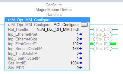
When you enable the configured AOI, you should see the Sts_MtdID tag get set by the device handler and the Sts_IP tag be briefly on. Once the connection has been established, you should also see the Sts_PC output toggle on. If the block produces an error, check the AOI’s help file for more information.
Step 5: Commanding Vehicles from the PLC
Now that your communications are all set up, you are ready to start controlling the Node Controllers from the PLC. While there are a lot of different things you can do from the PLC, we will start with the simple task of moving a single vehicle along your track.
First, verify the track is started up and functional using NC Host. For good measure, command a vehicle to move through NC Host to ensure that everything is properly set.
In the PLC code, navigate to the default raM_Dvc_DH_MM program and expand the Mover tag. Then, expand the entry for whichever vehicle you want to move and look at the MPM tags.
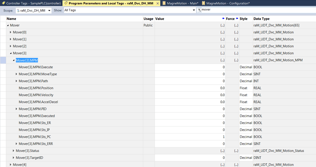
MPM stands for Motion Position Move and is a basic way to command a vehicle to move to a specified position. Inside this tag, set MPM.Path and MPM.Position to the path and position you want to move your vehicle to and set the MPM.Velocity and MPM.AccelDecel tags to whatever values would be appropriate for your system. Note: unlike NC Host which uses units of meters, the ICT library uses millimeters. Therefore, a value of 500 for Velocity means that the vehicle will move 500 mm/s.
Once your parameters are set, toggle the MPM.Execute bit and you should see your vehicle move across the track!
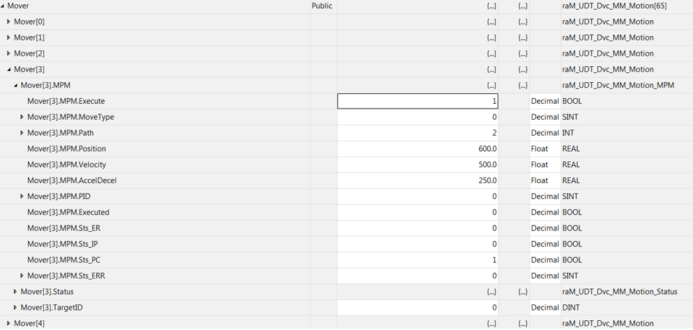
Note: If you get an error message in MPM.Sts_ERR you can check what the error code means by checking the help file of the AOI raM_Opr_MM_MPM
Topics to look forward to in this series:
Learn more about DMC's MagneMotion expertise and contact us to get started on your next project.