Emulating a controller is a useful way to test PLC code and an HMI project when physical hardware is not available. This blog will walk you through how to do so using Rockwell’s Studio 5000 and FactoryTalk VIEW ME.
1. Software Setup
To emulate, you must have four applications. This example will use Studio 5000 Logix Designer V31.01.00, FactoryTalk View Studio V10.00.00, Studio 5000 Logix Emulate V32.00.00, and RSLinx Classic V4.11.00. It is critically important to have compatible versions. Rockwell has more information on version compatibility.
2. Create PLC Project
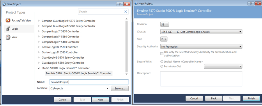
We will start in Studio 5000 Logix Designer and create a new project. When selecting a controller, select Emulate 5570 Studio 5000 Logix Emulate Controller. After clicking next, set the revision to 31 and put the controller in slot 2. We will explain the rationale for this latter.
3. PLC Programming
To keep the focus on emulation, we will use a simple PLC program for a solenoid valve. There are two programs in the MainTask: Inputs and Device Control.
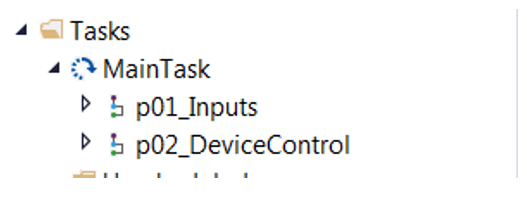
I have also included a picture of controller tags to help explain some of the tag definitions.

There are three rungs total in this project. One is an Add On Instruction or AOI in Device Control. The other two are for mapping inputs and outputs.
Here at DMC, we use AOIs to improve code modularity and save time. For a solenoid valve, we will use an AOI from DMC’s internal Rockwell library called AOI_ValveSolenoid. We will pass the AOI the tag Valve_HMI which is a user-defined data type. This data type is an InOut parameter for AOI_ValveSolenoid, so the AOI has read/write privileges. The Valve_HMI links information to display to the operator on the HMI via a global object. If you haven’t used global objects before, check out this blog.

Configuring hardware can be difficult using an emulated PLC, so we will work around this. We can simply have outputs energize the inputs. An implementation of this is shown below. This trick saves the time of setting up the hardware configuration in the Logix Designer and Logix Emulate.

To give more context on the exact tags I have used, Valve_Device is the instance data type of our solenoid valve AOI. bOutHome is an output of the AOI and is true when the device is in the home position. We will have bOutHome energize bInSignalHome, which is an input showing that the feedback on the home position is true. Thus, when we command the valve we will see the inputs match.
4. HMI
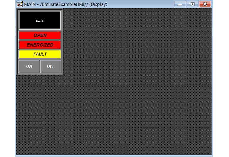
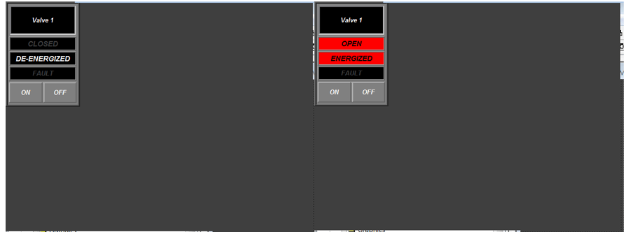
The HMI will also be simple with one global object instance to display the state of the solenoid valve and allow for control. The On and Off buttons are commands to open and close the valve. The fault indicator turns on if feedback does not match the command. The energize indicator is true when the valve moves to the work/open position. Open will light up if the valve is in work/open. Finally, the S…S will take a string defined on the PLC for the name of the valve.
5. Emulate
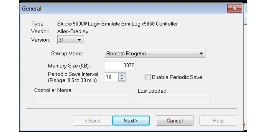
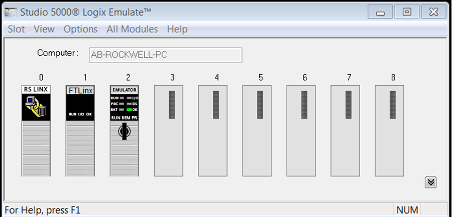
Now, that we have a PLC program and an HMI display made it is time to emulate the controller. Open Studio 5000 Logix Emulate. You will see the RSLinx Classic module in slot 0. If FactoryTalk Linx is installed on the computer, slot 1 will have a FactoryTalk Linx module. If these modules are not present, it is likely a sign that one of these applications is not installed or has version conflicts. Next, right-click slot 2 and select create. A Select Module box will appear where you can select Emulate 5570 Controller and click OK.
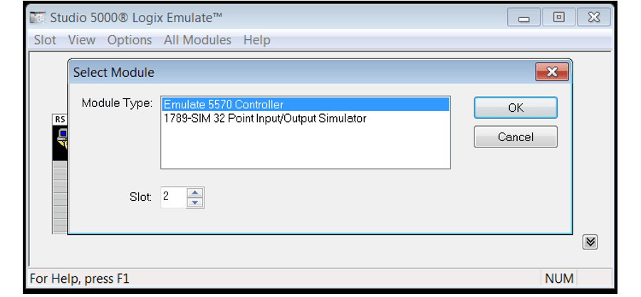
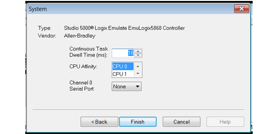
In this example, we will select version 31 for the controller to be consistent with the Logix Designer project. The other settings on the General window and the System window can be left as default unless your project has specific requirements.
When you are finished Studio 5000 Logix Emulate should like this:
6. RSLinx
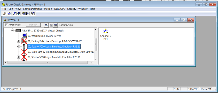
Open RSLinx Classic and select Communications>RSWHO. A popup should appear as shown below. Select slot 02 Studio 5000 Logix Emulate. You must leave RSLinx Classic running.
7. Download PLC Project to Emulated Controller
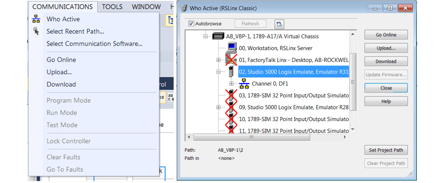
In Studio 5000 Logix Designer, select COMMUNICATIONS>Who Active to bring up a popup window. In the window, you should see in slot 02 a Studio 5000 Logix Emulate controller. Select the controller and click go online.
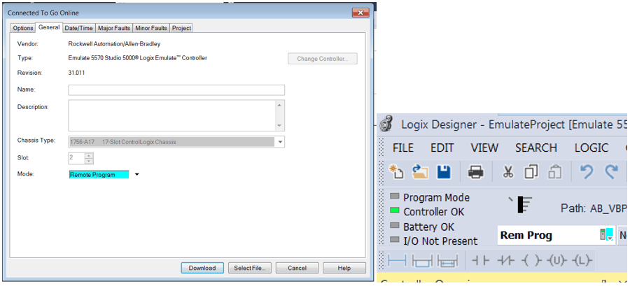
Another popup like the one below should appear. You can select download. Either before or after the project has downloaded you may switch from Remote Program (Rem Prog) to Remote Run (Rem Run). Before downloading, the mode can be changed, or afterward, there is a drop-down selection for the mode in Logix Designer. The differences between the two modes are not consequential when emulating, as there is not any real I/O connected.
After moving the controller to run, you will see green bars on your PLC logic indicating you are online with the controller.

Congratulations, you have successfully downloaded to an emulated controller! You can test and make edits to your project at this stage. You can even force bits true to test your program. Continue with the steps below if you would like to link up the HMI as well.
8. FactoryTalk Linx
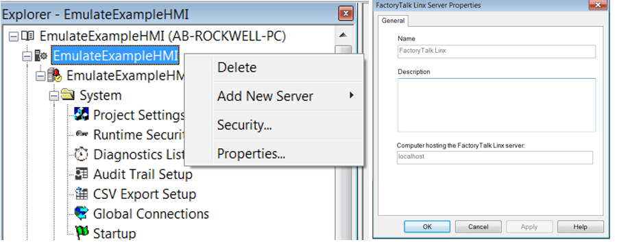
To connect your HMI project to the emulated controller you have to setup FactoryTalk Linx in FactoryTalk View ME. To setup FactoryTalk Linx, right click on the name of your project in the explorer menu within FactoryTalk View. In my case, my HMI Project was called EmulateExampleHMI. Select Add New Server>Rockwell Automation Device Server (FactoryTalk Linx). A window will popup where you can hit OK. You may see an error if FactoryTalk Linx has already been set up for your project. That is okay you can simply proceed to the next step.
In the Explorer, open Communication Setup under the newly added FactoryTalk Linx icon. Under device shortcuts select Add. I like to name the shortcut PLC.
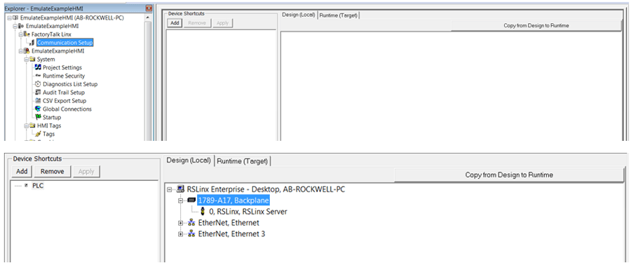
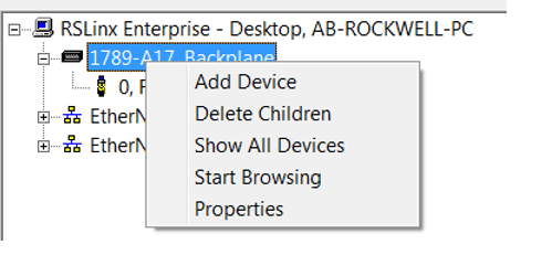
It may take a second to load, but you will eventually see something like what is shown below. If you right-click 1789-A17 Backplane select Add Device you will be able to a 1756-Lx/Em, ControlLogix 55xx Emulator. Be sure to expand by clicking the plus icon and select revision 31.
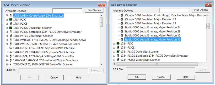
Select slot 2 for the controller to match our previous selections in Logix Emulate and Designer.
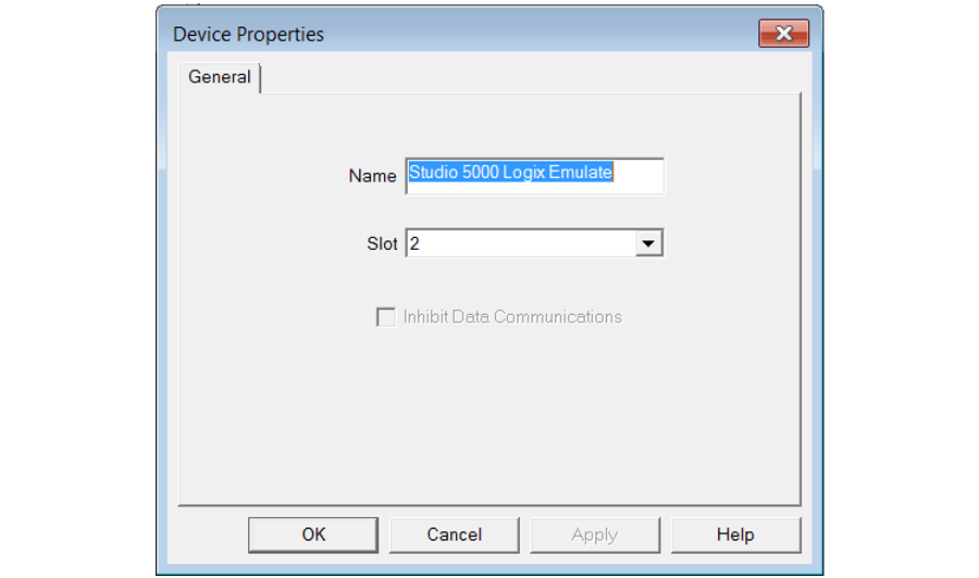
Now, the HMI knows where to look for tags from the controller. If you go to one of the HMI displays you made earlier, you can right-click on a Global Object instance to specify the Global Object Parameter Values. Click on the three dots under Tag to bring up the Tag Browser.

Click on Refresh All Folders to make sure that the HMI is looking at the latest version of the tags on the controller. We named the shortcut PLC, so we see it appear on the left side. Through expanding the list and then expanding Online a list of tags from the PLC project will appear. To link the Global Object select the appropriate tag. In my case, I will select Valve_HMI and click OK.

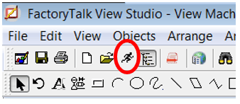
You are finally ready to simulate the HMI. Select the running man icon under Objects to simulate the HMI project.
After loading a simulated HMI will appear. By clicking ON and OFF the valve can be open and closed.
Emulating can be a bit of a challenge but well worth it to test an HMI and PLC project. If you have more questions about emulating, comment below. If you need Rockwell PLC or HMI support, reach out to us at DMC.